Cherokee
Radios CBS2100
Documentation Project
CBTricks.com
TRANSMITTER ALIGNMENT
Note: Unless otherwise specified, adjust Mic Gain control on the front panel to fully clockwise position for all following tests.
A. Test Set-Up
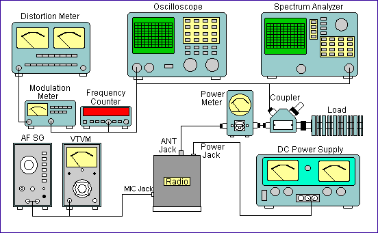
Set up test equipment with the CBS-2100 radio as indicated below:

B. SSB Balanced Modulator Adjustment
| 1. | Set the mode selector to USB, and the channel select to CH 20. |
| 2. | Adjust Mic Gain control on the front panel to minimum (fully counterclockwise). |
| 3. | Press PTT to transmit on SSB without modulation. |
| 4. | Adjust VR7 for minimum RF output. |
| 5. | Check RF output on LSB is also minimum. |
| 6. | Resume Mic Gain control to maximum setting (fully clockwise). |
C. RF Power Transistor Bias Current Adjustment
| 1. | Set the mode selector to USB, and the channel select to CH 20. |
| 2. | Remove the short link PCB (installed vertically in front of the RF Power transistors). |
| 3. | Connect 100MA FS DC current meter to TP-9 [+] and TP-8 [-]. |
| 4. | Adjust VR11 for 60mA � 3mA to TR44. |
| 5. | Connect 200mA FS DC current meter to TP-9 [+] and TP-7 [-]. |
| 6. | Adjust VR10 to 100mA � 5mA to TR43. |
| 7. | Install the short link PCB back to the holder of TP-7, TP-8 & TP-9 upon completion of adjustment. |
D. AM RF Power Output Adjustment
| 1. | Set mode selector to AM. |
| 2. | Select the channel selector to CH-20. |
| 3. | Press PTT to transmit. |
| 4. | Adjust VR-13 for 4W RF Power output. (Without modulation) |
E. RF Power Amplifier Adjustment
IMPORTANT: VR-12 Bias adjustment, should not be rotated clockwise beyond 2 o'clock position, otherwise the RF transistor may be destroyed.
| 1. | Set the Mode Selector to USB. Compander OFF. |
| 2. | Apply 1 KHz 50mV RMS audio signal to Microphone input connector pin 2. |
| 3. | Set the Channel Selector to CH-20. |
| 4. | Press PTT to transmit. |
| 5. | Adjust VR-12 and L-42 for Maximum RF power output as read on the RF Watt Meter. |
| 6. | Adjust L-40, L-43, L-44 and L-33 for max. RF power output. |
| 7. | Repeat step 4 to 5 until no further improvement is obtained. |
| 8. | Adjust L-42 for balanced RF Power output on CH40 & CH1. |
| 9. | Switch to AM Mode, disable audio signal generator, press PTT to transmit. |
| 10. | Adjust VR-13 for 4W RF Power output on AM Mode with no modulation. |
| 11. | Switch back to USB Mode, apply 50mV 1 KHz audio, press PTT to transmit. |
| 12. | Switch VSWR meter to Peak Detection Mode. |
| 13. | Adjust VR-12 for max, 12W SSS Peak Power Output. |
F. AM Modulation Adjustment
| 1. | Apply 1 KHz 50mV rms. AF signal to Microphone input connector pin 2. |
| 2. | Activate PTT to transmit in AM Mode. Compander (CDS) OFF. Adjust VR-14 for 90% modulation. |
G. Compander (CDS) Functional Test - Transmitter
| 1. | Apply 1KHz 2mV rms. AF signal to Microphone input connector pin 2. |
| 2. | Activate PTT to transmit in AM Mode. Compander OFF. |
| 3. | Observe modulation level between 20-80%. |
| 4. | Switch Compander (CDS) to ON /Auto CDS. |
| 5. | Observe the modulation level increases to around 90%. |
| 6. | Increase signal generator level from 2mV to 100MV, Compander (CDS) ON Auto CDS. |
| 7. | Observe the modulation level remains to be less than I 00%. |
| 8. | Repeat the test with CDS ON and Super CDS set to Maximum. |
H. Advanced Test Procedures for Modulation
Following advanced test procedure requires optional / advanced test equipment setup by experienced technical person, and is not normally required in a field repair environment.
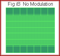
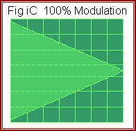
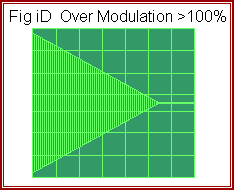
| Modulation Level = (a-b) X 100% ÷ (a+b) | 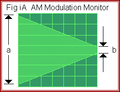 |
 |
 |
 |
i) AM Modulation Monitor
| - | Apply 1KHz 50mV rms. AF signal to Microphone input connector pin 2 of the radio, and to the Y input (Usually marked as Timebase) of the oscilloscope. |
| - | Monitor RF output waveform with X input (usually marked as CH 1) of the oscilloscope. |
| - | Activate PTT to transmit on AM Mode. Cornpander (CDS) OFF. |
| - | Confirm the AM Modulation displayed in the oscilloscope is less than 100% as in Fig iA. |
ii) SSB Modulation Monitor
| - | Use two AF signal generator connected in a star resistor network to provide a balanced 3 input/output ports with impedance of 600ohm. Compander OFF. |
| - | Apply 500Hz and 2.4KHz 30mV audio tones signals simultaneously through the resistor network to the Microphone input connector pin 2. Activate PTT to transmit on USB Mode. |
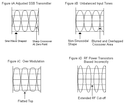
| - | Adjust the output level of the 500Hz AF signal generator to obtain the proper waveform on the oscilloscope as shown in figure iiA. (See Fig C to D for waveforms of improperly set up radios) |
iii) FCC Emission Limitation Check
| - | Set up equipment as in i) AM Modulation Monitor Test, Compander OFF. |
| - | Couple the Spectrum Analyzer input to the RF Dummy Load |
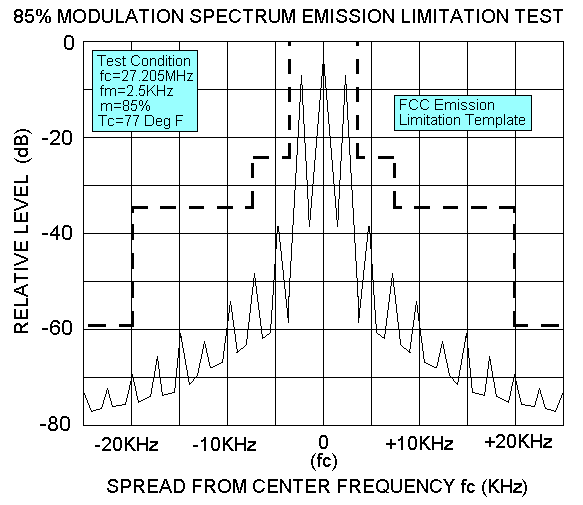
| - | Apply 2.5KHz 50mV rms. audio tones signal to the Microphone input connector pin 2. |
| - | Activate PTT to transmit on AM Mode, adjust AM Modulation level to 85% (see Fig iA). |
| - | Observe on the Spectrum Analyzer that the Radio's RF output are within the FCC limits |
| - | Repeat test with Compander (CDS) ON and Super CDS turned to Maximum. |
