Galaxy
DX Radios DX979
Documentation Project
CBTricks.com
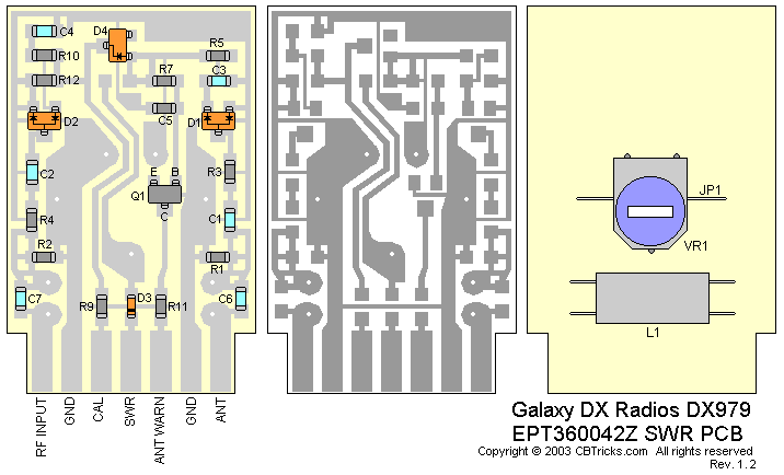
SWR PCB Layout (EPT360042Z)
Schematic

|
Ref#
|
Description |
MFR. Part No. |
|
|
SWR PCB EPT360042Z Complete with Components |
#T-145W-P10 |
|
|
SWR P.C.B. 33x25x1.6tmm (S) |
EPT360042Z |
Resistors
|
Ref#
|
Description |
MFR. Part No. |
|
R1 |
CHIP/F/R (SMD) 470 OHM 0.1W |
RCY014714Z |
|
R2 |
CHIP/F/R (SMD) 330 OHM 0.1W |
RCY013314Z |
|
R3 |
CHIP/F/R (SMD) 100 OHM 0.1W |
RCY011014Z |
|
R4 |
CHIP/F/R (SMD) 100 OHM 0.1W |
RCY011014Z |
|
R5 |
CHIP/F/R (SMD) 1K OHM 0.1W |
RCY011024Z |
|
R7 |
CHIP/F/R (SMD) 10K OHM 0.1W |
RCY011034Z |
|
R9 |
CHIP/F/R (SMD) 0 OHM 0.1W |
RCY010004Z |
|
R10 |
CHIP/F/R(SMD) 2.2K OHM 0.1W |
RCY012224Z |
|
R11 |
CHIP/F/R (SMD) 1K OHM 0.1W |
RCY011024Z |
|
R12 |
CHIP/F/R(SMD) 2.2K OHM 0.1W |
RCY012224Z |
Capacitors
|
Ref#
|
Description |
MFR. Part No. |
|
C1 |
CHIP/C (SMD) 0.001UF 50WV Z SL |
CK1102AB7L |
|
C2 |
CHIP/C (SMD) 0.001UF 50WV Z SL |
CK1102AB7L |
|
C3 |
CHIP/C (SMD) 0.1UF 25WV Z Y5V |
CK2104AB7R |
|
C4 |
CHIP/C (SMD) 0.1UF 25WV Z Y5V |
CK2104AB7R |
|
C5 |
CHIP/F/R (SMD) 10K OHM 0.1W |
RCY011034Z |
|
C6 |
CHIP/C (SMD) 3PF 50WV C CH |
CK1030AB1A |
|
C7 |
CHIP/C (SMD) 0.5PF 50WV C CH |
CK1059AB1A |
Inductors
|
Ref#
|
Description |
MFR. Part No. |
|
L1 |
(CME) BRAND CORE BF 2159576 |
ECRFZ10204 |
Transistors
|
Ref#
|
Description |
MFR. Part No. |
|
Q1 |
T/R (SMD) 2SC2712GR-TE85L |
TY2SC2712G |
Diodes
|
Ref#
|
Description |
MFR. Part No. |
|
D1 |
DIODE (SMD) HSM198S |
EDHM0198SY |
|
D2 |
DIODE (SMD) HSM198S |
EDHM0198SY |
|
D3 |
DIODE (SMD) 1SS355 |
EDSS00355Y |
|
D4 |
DIODE (SMD) MA28T |
EDMA0028TY |
Potentiometers
|
Ref#
|
Description |
MFR. Part No. |
|
VR1 |
S/F/R 10K OHM L |
RE10300009 |
Wire Jumpers
|
Ref#
|
Description |
MFR. Part No. |
|
JP1 |
JUMPER WIRE 7x15x7mm |
WX01070715 |
Disclaimer: Although the greatest care has been taken while compiling these documents,
we cannot guarantee that the instructions will work on every radio presented.