The following describes the installation procedure for adding the Viagra "A" channel modification PCB to the Galaxy DX949,DX959 and DX2547. Although this accessory can be added to any EPT06960Z Main PCB.
Preparing the Radio for the Mod.
1. Fully check out the radio and be sure everything works before starting this mod!
2. Carefully remove the top and bottom radio covers. When removing
the bottom cover, disconnect the speaker connector from the main board.
3. Using the provided screw, mount the Viagra "A" PCB through the open hole in the chassis, just behind the channel selector location. Use the hole which is closer to the center of the chassis.
4. Locate J4 on the main board. It is located near the front-right of the board as you are viewing it. Remove J4.
5. Locate J14 on the main board (EPT06960Z).
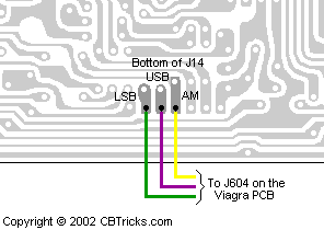
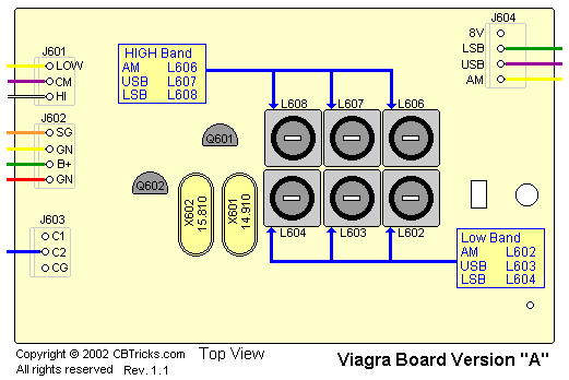
6. Route the Green, Purple and Yellow wires from J604 on the Viagra A board under the front of the EPT06960Z and to the underside J14 on the EPT06960Z board.
7. On the solder side of J14 on the main board, (a) solder the Green wire to the LSB pad, (b) solder the Purple wire to the USB pad (c) solder the Yellow wire to the AM pad.

11. Route the Blue wire from the Viagra A board J604 to the solder side of the EPT06960Z board. Solder this wire to C2 on J9.

9. Early production models did not have J28 installed on the main
pcb but the J28 jack came with the Viagra A kit. If J28 is missing follow
the next step. If J28 is installed plug in the plug from J602 on the Viagra
PCB to J28.
Route the Orange,
Yellow, Green, and Red wires from J602 on the Viagra "A" PCB
to the vacant J28 connector holes on the component-side of the EPT06960Z
board.Make the
connections as follows:
Orange wire to SG on J28
Yellow wire to GN on J28
Green wire to B+ on J28
Red wire to the last open hole.

10. The Viagra A PCB were designed to use the OFF/ANL/ANL+NB switch by plugging into J6 on the main pcb. Some folks use the tone switch (HI/MED/LOW) on the front panel or you can mount a center switch in the radio.

Final Steps and Alignment
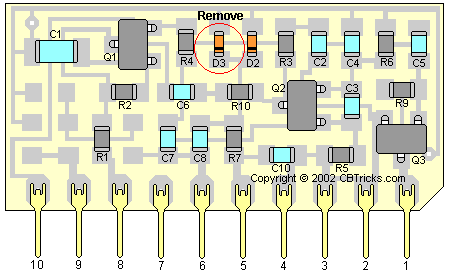
NOTE: The early production (1st year) models had D3 on the VCO PCB installed. The later models it was removed. If you have one of the early radios you will need to do the next 3 steps.
1. Locate the VCO PCB at the front of the radio. This is the small,
vertical surface-mount board which is covered in a black coating.
2. On the portion of the board facing the front of the radio, count over four (4) components on the top row. This is diode D3.

3. Remove D3
from the VCO PCB. If you do not know how to remove surface-mount components,
stop at this point and find someone and get help.
Alignment Procedure
