Click to see close up
INTRODUCTION
This section explains the basic operating procedures for the RCI-2950/2970 amateur 10 meter mobile transceiver.
CONTROL & CONNECTIONS
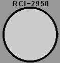
1. FREQUENCY SELECTOR:
This control is used to select a desired transmit and receive frequency.
It enables you to make a continuous tuning over the entire range of the
transceiver.
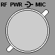
2. RF POWER CONTROL:

This control enables you to adjust RF power continuously over the range
of 1 watt through 25 watts
(RCI-2970: 10 watts through 100 watts).
3. MIC GAIN CONTROL:
This control adjusts the microphone gain in the transmit and PA modes.
This feature is designed for use in a
h-ambient noise environment or to maxize talk power.
4. ON/OFF VOLUME
CONTROL: 
Turn clockwise to apply power to the radio and to set the desired listening
level.
5. SQUELCH CONTROL:
This control is used to control or eliminate receiver background noise
in the absence of an incoming signal.
For maximum receiver sensitivity, it is desired that the control be adjusted
only to the point where the receiver background noise is eliminated. Turn
fully counterclockwise then slowly turn clockwise until the receiver noise
disappears. Any signal to be received must now be slightly stronger than
the average received noise. Further clockwise rotation will increase the
threshold level which a signal must overcome in order to be heard. Only
strong signals will be heard at a maximum clockwise setting.
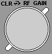
6. RF GAIN CONTROL:

This control is used to reduce the gain of the RF amplifier under strong
conditions.
7. CLARIFIER CONTROL:
This control is used to fine tune the received signal for the maximum
clarity in SSB or OW mode. It can adjust
the receive frequency about + / - 500 Hz, but does not affect the transmit
frequency or the frequency display.
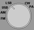
8. MODE SWITCH:

This switch allows you to select one of the six following operating modes:
FM, AM, USB, LSB, CW, and PA.
9. NB/ANL BUTTON:
![]()
The noise blanker is very effective in eliminating repetitive impulse
noise such as ignition interfer-
ence. In the ANL position, the automatic noise limiter in the audio circuits
is activated.
10. ROGER BEEP
BUTTON: ![]()
This button activates the ROGER BEEP Circuit when its function is selected.
11. SPLIT BUTTON:
![]()
This control enables you to split an operating frequency for FM Repeater
operation.
12. PROGRAM BUTTON:
![]()
This button is used to program operating or scanning frequencies into
memory. See the OPERATION section of the manual for further details.
13. MANUAL BUTTON:
![]()
This is used to return the unit to manual mode.
14. SHIFT BUTTON:
![]()
This is used to select 100Hz, 1kHz, 10kHz, 100kHz or 1MHz frequency steps.
15. DIM BUTTON:
![]()
This button adjusts the display backlighting in four different steps to
best match the environment.
16. SWR BUTTON:
![]()
This control is used to check SWR.
17. SCAN BUTTON:
![]()
This is used to scan frequencies in each band segment. The OPERATION segment
of this manual provides
detailed information on using the SCAN control.
18. MEMORY BUTTON:
![]()
This button is used to program memory channels. Detailed information on
how to use this control is provided in the OPERATION section of this manual.
19. ENTER BUTTON:
![]()
This is used to program frequencies in memory. See the OPERATION section
of this manual for more information on using this control.
20. LOCK BUTTON
: ![]()
This button is used to lock a selected frequency. Press it activate the
switch. In this position, it disables the Frequency Selector Control,
up/down buttons on the front control panel, or remote up/down buttons
on the microphone. Repressing the switch will unlock the frequency.
21. UP/DOWN SELECTORS:
![]()
![]()
These buttons are used to move frequency upward or downward to select
a desired frequency.
22. METER:
This meter indicates received signal strength, transmitter RF output power
and SWR level.

23. LCD DISPLAY:
The LCD displays the frequency selected, functions and memory channel.
24. MIC JACK:

Accepts 6 pin female connector with a type Philmore T6160 and Calrad 30445
to be connected.
