TRANSMITTER (Refer to Fig. 6)

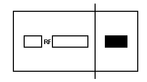
Fig. 5 Connections for Transmission Adjustment
1. Adjustment
for Transmission should be connected as shown in Fig. 5.
Initially set each knob as follows:
a) Channel Selector Switch 19CH
b) PA - CB Switch CB
c) Mode Switch USB
d) MIC GAIN CW - Max
e) Other knobs Optional
Set conditions for
TX as follows S1 & S2: "OFF", ON _OFF/VOLUME "ON",
&
adjust PTT to TX mode. Remove TP8 & insert DC mA meter, adjust VR9
for
current to obtain within 60mA+/-5mA.
2. Remove TP7, insert DC mA meter, adjust VR8 for current to obtain 60mA+5/-0mA. Futhermore, when current does not reach 60mA, rotate semifirxed VR8 to max CCW. After finishing these adjustments, do not hang TP7, TP8.
3. Rotate VR11
to Max CW.
AF OSC1 should be 500Hz, AF OSC2 2400Hz & switch S1 & S2 to "ON"
Decrease AF ATT & adjust L47, L48 to reach peak while sustaining indication
of RF
Voltmeter to 15-20V,
4. Next, place the core of L45 up to bottom part & adjust L46 to it's peak. Hereafter, L46 should be not moved. Then, interchange Channel switch one after the other to 1 CH & 40CH. Adjust L45 remove output deviation, afterwhich change Channel switch back to 19CH.
5. Set Mode switch to "AM". combine AF OSC1 to 1KHz & turn S1 'ON', S2 "OFF'. Decrease AF ATT & add input of 15mV. Adjust L38 to obtain maximum reading, reaching its peak as to be indicated by RF voltmeter.
6. Also turn
"OFF" S1 & Mode switch to "USB'. Observe the carrier
flow in the Oscilloscope & Spectrum Analyzer & try to exchange
alternately Mode switch to "USB' & "LSB'. Value of carrier
flow is same as others & moreover, that value is to be adjusted for
VR4 to obtain min, reading.
7. Combine AF OSC1 to 500Hz, turn S1 & S2 "ON". Decrease AF ATT to 5mV input & adjust VR11 to obtain 24.5V to be indicated by RF voltmeter.
8. Set Mode switch to "AM" & S1 & S2 'OFF", NO MOD conditions; adjust AM transmitter output to 4.OW at VR10,
9. Adjust VR6.

10. Observe No. 2 RF with the spectrum analyzer & RF meter; adjust L36 to obtain minimum reading at the level.
11. Check if SWR meter is working normally.
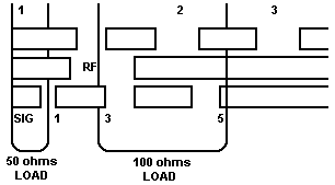
| 11 - 1 | 50 ohms load | 1.2 or less |
| 11 - 2 | 100 ohms load | 1.5 - 2.5 |
12. Make analysis based on the other specifications,
1.3 At 1KHz 50% MOO +16dB input, adjust VR7 for alignment of AM to reach 90%.

NOTE: BEFORE TURNING THE UNIT TO 'CAL" MODE, BE SURE THAT THE CAL CONTROL IS MINIMUM (CCW).

Fig. 6 TX Adjustments