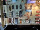
This was a high-end accessory, sought after when it was new 45 years ago. Doesn't look so terribly special now.
The digits are only lighted one at a time. Switching circuits feed the desired pattern of 7 segments into all the digits wired the same. But since only one turns on at a time, this saves a lot of wires. Called "multiplexing". The digits flash on, then off in sequence fast enough to cause flicker fusion and makes them appear to be illuminated all the time. The digit on/off patterns for the clock come from the fat 24-pin MM5314 chip.
The digit pattern for the frequency counter comes from another fat chip, the one marked "7208".
A set of 3 chips marked "4016" serve as the traffic cops. Either one or the other of those two fat chips feeds control voltages to the digits, by way of six NPN transistors Q11 through Q16. They serve to switch only one digit on at a time, the turn the other five off. The 4016 chips alone can't deliver enough drive current to meet the needs of the LED digits. The six transistors each provides a current boost to one digit at a time.
A problem that is only seen while the radio is transmitting points us to the frequency-counter side of this setup.
The diagram doesn't indicate which 4016 chip powers the left-most digit. Has to be caused by something that is NOT shared between clock and counter modes.
That chip is on the list of suspects.
The 7208 frequency counter chip is long obsolete and hard to find. It feeds into the 4016 chip that drives that left digit.
But those are the two things that seem most likely. The 4016 (diagram won't tell you which) and the 7208.
Everything else associated with that digit is shared by clock and counter modes both.
73


