• You can now help support WorldwideDX when you shop on Amazon at no additional cost to you! Simply follow this Shop on Amazon link first and a portion of any purchase is sent to WorldwideDX to help with site costs.
  • Click here to find out how to win free radios from Retevis!

Galaxy Saturn growling noise from echo board

The parts-placement diagram in the Thomas book shows the ghostly-gray foil traces. Also the board number, but not quite clearly enough to make out. It's a mirror image of "EPT36001(glob)". It's on the board's edge just forward from the speaker amp chip.

It's definitely one or more revisions older than the "-14" versions sold from the mid-90s to the mid-2000s.

73
 
Hi RF Krazy, I finished the truck, gotta take it in for an alignment at 8:30. I got the toe in/out set pretty close just eyeballing it, but the camber/caster adjustment is beyond me so I just set it like it was. Drives like a new truck again, even without an alignment. Alright, enough shop talk. When I get back, I will look over the schematic and give you some points to check.
So, from what I gather, when you soldered the connections wrong, you just tied the mic audio input to ground, right?
Do you think you may have applied echo board power to mic input when jumpering?
Gotta figure out what was fed to the mic input.
Say, do you have a scope?
Hello cable Guy,

Yeah camber/caster is for the shop that has the alignment equipment. But Hey, if it drives like a new one, you must had gotten pretty darn close! Good Job.

Yes, I wired the mic audio to pin 1, mic ground, and mic ground to mic audio, reversing the wires on the radio mic jack.

Some how or another is when the growling had started. At one point I had even tied the chassie ground to PTT.

The only wires I believe I had crossed on the echo board are the input/output and the the PTT wires. What ones I had actually cross together, I now do not remember. But I am pretty sure I did not cross any "hot" wires so to speak.

As far as crossing echo power wires to mic input, I don't believe so, but at this point, I wouldn't rule it out, I am sorry to say.

On the echo board that I have, there are also wires that get connected on the side of the board. The wire colors are Y, Green, Blu, and Purple. Green has been cut and not connected. Can someone tell me what these wires are?

I have a scope, but since I had moved, I cannot find the leads. I have an old Tektronix 465. I will continue to look for them, but I have a lot of stuff still in bins that are hard to get to, but never the less.

I have been studying the the schematic, and making a Shot Gun Parts list for now.

Some parts I cannot find online. There is one company that demands a $250.00 minimum. It seems the more expensive parts company "RF Parts", has more to offer than Mouser and Newark. I will probably order a little from each, depending on the total shipping cost. It may be cheaper to spend more then less when compared to spending more on shipping on more then one company at a time?

I have been trying to draw out a sketch of my wrongfully reverse wiring scheme to compare it to the schematics to help me see things more clearly.

Has anyone ever seen an OP amp weaken instead of just being shorted or opened? Looking at the schematics, the Op amp inputs are 3, and 5. From what I can see, 3 is the main mic audio input. I think 1 and 7 are the out puts.

I am suspecting the lower audio is due to something on the input side of IC4 the Op amp???

Anyway Cable Guy, I am glad to hear you have your truck back together. I am sure that is a relief.

Thanks again for helping.

RF Krazy
 
The parts-placement diagram in the Thomas book shows the ghostly-gray foil traces. Also the board number, but not quite clearly enough to make out. It's a mirror image of "EPT36001(glob)". It's on the board's edge just forward from the speaker amp chip.

It's definitely one or more revisions older than the "-14" versions sold from the mid-90s to the mid-2000s.

73
Hello Nomadradio,

Thank you for bringing this to our attention. As mentioned in my previous post...

"I have been studying the the schematic, and making a Shot Gun Parts list for now." And to have them on hand.

I am hoping this gets figured out with what's causing the low audio so to learn from it all, instead of just swapping parts. I have never done something as stupid as this to see the results that I am seeing. It is a little unusual from what I have ever seen.

I don't think with the echo board inline that it amplifies the audio with the echo switch turned off does it? The echo board at this point is no loger working to try to see any results.

Anyway, thank you again Nomadradio, that schematics surly does help.

RF Krazy
 
I keep going back to the growl and low mic occuring after replacing the finals. The growl is in rx and mic is low. I can't help but think the growl is oscillation in the PA section, possibly from biasing incorrectly. Also wondering what caused the old finals to death nap. Could also explain the low mic, as there isn't enough headroom to add audio, if the oscillations are consuming your output. Even the growl, if the pa is oscillating, could pop into the Rx, if oscillating at random frequencies. I don't think grounding the mic input would bother the mic amp too much, but you can check the 10k resistor R187 and see if it's correct ohms or darker in appearance, possibly burnt. I haven't seen an op amp go weak before. I'm just stuck on the final replacement, unless I'm ignoring something posted earlier, I do speed read these posts sometimes, often many times. I'm gonna read it all again, slower.
 
Oh, I listened to your growl, I have heard something like that before, just can't remember what it was or where. If it comes to me, I'll let you know.
 
I keep going back to the growl and low mic occuring after replacing the finals. The growl is in rx and mic is low. I can't help but think the growl is oscillation in the PA section, possibly from biasing incorrectly. Also wondering what caused the old finals to death nap. Could also explain the low mic, as there isn't enough headroom to add audio, if the oscillations are consuming your output. Even the growl, if the pa is oscillating, could pop into the Rx, if oscillating at random frequencies. I don't think grounding the mic input would bother the mic amp too much, but you can check the 10k resistor R187 and see if it's correct ohms or darker in appearance, possibly burnt. I haven't seen an op amp go weak before. I'm just stuck on the final replacement, unless I'm ignoring something posted earlier, I do speed read these posts sometimes, often many times. I'm gonna read it all again, slower.
Hello Cable Guy,

Yeah I really don't know at this point, but I was the cause.

I say this because I was trying to key an external box that needed a PTT to RCA
in order to key the box. I was just testing the radio and decided to key the box by just grounding out the RCA to bring in the relay. Well the RCA jack was not even mounted, meaning it was just balancing on the bench while I was trying to short it out while keying the mic. Yeah I know...It had disconnected and then reconnected during transmit, and the next thing I know the finals had blown.

As for the 10k resistor, I don't think it had gotten shorted or open, but I did see it on the schematic.

It won't hurt to check it.

I really need to be able to adjust the BIAS regardless, so I will have to try to find those final pots somewhere online.

Does anyone know where to purchase them? And what are their values? Also I think I read somewhere they should be at least a 1/2 a watt.

Actually does anyone have a better source where to get parts for this radio besides RF Parts, Mouser, Newark Electronics or ???

Thank you all who have chimed in to help. I will be checking on more voltages that the service manual recommends. Of course if I find anything I will certainly post it here.

And again Cable Guy, Thank you for helping. I think it was you who mentioned about changing out the old caps. I will eventually be doing that as well. I think I had counted like 42 caps on the main board, so that will be a slow process.

Again Thank you.

RF Krazy
 
Last edited:
I think it was you who mentioned about changing out the old caps. I will eventually be doing that as well. I think I had counted like 42 caps on the main board, so that will be a slow process.

Again Thank you.

RF Krazy
There is a great source for quality cap kits lurking around the forum, @Klondike Mike has always fixed me up, and it's quicker and likely cheaper getting a kit, as buying quality capacitors sometimes have a minimum order, and many different values. See if he can fix you up. His kits have had all the caps needed for a single chassis.

 
Hello Xracer13,

This will be a big help, as I really didn't know where to turn. Funny though, I have been to this site from time to time, but I wasn't searching for anything in particular. And it had been a long time, so I had totally forgotten about it.

Thanks a bunch for the link. The ones here aren't the plastic ones. So I am not sure if the reason I cannot adjust the finials are actually due to these pots, but being old in the tooth as I had heard one say, I would like to replace them anyway.

A Big Thank You for the link. Now to fine the value of them...

RF Krazy
 
There is a great source for quality cap kits lurking around the forum, @Klondike Mike has always fixed me up, and it's quicker and likely cheaper getting a kit, as buying quality capacitors sometimes have a minimum order, and many different values. See if he can fix you up. His kits have had all the caps needed for a single chassis.

Hello Cable Guy,

I have been away from my bench PC, and for some reason I cannot login from my cell phone. I have been creating a list of parts. Hopefully I will be able to hunt down all of them.

Thank you for the idea of getting them from Klondikemike, I will look into this for sure.

You and everyone else have been a great help, Thank you.

RF Krazy
 
  • Like
Reactions: jrd426
Hello,

Thank you again Xracer13, and of course thank you to all who have been helping, not only with this particular subject but also with my other subject pertaining the same radio in another Post.

I now have quite a bit of parts but I am still in the process of trying to order more.

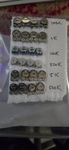
I placed a pic here of the variable resistors needed for the bias adjustment of the finals.

As seen in the pic I had bought several! I hope two of them I can actually use.

I am hoping someone here can tell me the actual values for the final transistor's variable resistors for the Galaxy Saturn.

I haven't given up as of yet, but without the help that I have been given, I probably would have.

Thank you,
RF Krazy
Hello,

Thank you Xracerx13 and everyone who have been helping including those who have helped in a previous Post about the same radio.

I have bought quite a few parts in the meantime and I am still searching for some more.

Because of you Xracerx13 I was able to purchase some variable resistors for the finals. However, I was not sure of the values, so as seen in the Pic I bought several.

Is there anyone who knows the actual values of the needed variable resistors for the finals. Apparently there are two different values. I think the final adjusters are VR20 being the first final and VR10 being the second final adjuster if you will.

Thank you,
RF Krazy
 

Attachments

  • variable resistors.jpeg
    variable resistors.jpeg
    62.8 KB · Views: 7
The value is written on your original variable pots. If they are dirty clean them with alcohol. If you can't see them cause they are too small, use a magnifying glass.
According to the schematic I posted which I am not sure matches your radio exactly the driver VR11 should be 1K, and the final VR10 closer to the antenna jack should be 100 ohm.
Thank you Xracerx13,

I have never had to replace these, not even once, so I really had no idea accept
maybe to take them out of the circuit and ohm them out.

Now with that being said, these variables here are the metal ones. What I do see is the number 101 engraved into them for the final with a wierd symbol that doesn't look like the omega symbol for ohms, and then the letter "A".

Now with what you had said holds true for the new ones that I had recently purchased. Now there are two variables for the finals due to having two actual finals installed. So should I assume the variables are 100 Ω s ?

I guess if I am going to change them, I could ohm them out to see if I could get a reading anyway.

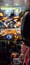
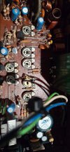
I added a pic of one of the variables for the finial hoping one can see what I am seeing!

The other pic of the variables are just in general to show that most of them have a sticker with a number. I guess this number is there so it can be found on the "BOM" or the schematics. I don't remember this from the past in the late 70's to early 80s, but I probably just don't remember.

Anyway Xracerx13, I appreciate your help in any means.

Thank you,
RF Krazy
 

Attachments

  • Finial variable.jpeg
    Finial variable.jpeg
    90.2 KB · Views: 4
  • marked variables.jpeg
    marked variables.jpeg
    100.1 KB · Views: 4
101=100 ohm
102=1k ohm
103=10k ohm
104=100k ohm
105=1M ohm
Hello Xracerx13,

Wow! You just taught me something that I have never come across. As I had mentioned, I have never had to replace these and so I never really paid any of attention to their actual values or how to verify them.

Sorry its been a while since I have checked in. There has been a lot going on in my neck of the woods that has kept me away from the radio world.

I would like to ask if their is anyone who has a clearer schematic that can clearly identify what leads of the caps that piggy back the finals are actually soldered to.

From what I can see, one pin goes to the Emitter and the other pin goes to the far left of the Base, but not the Base itself but on another connection on the board. In other words, only one pin of the cap gets connected to only one lead of the final, which is the Emitter. Is this correct with what I am seeing on the schematic?

Again a Big Thank You Xracerx13 for teaching me something that I did not know.

RF Krazy
 

dxChat
Help Users
  • No one is chatting at the moment.
  • @ kopcicle:
    If you know you know. Anyone have Sam's current #? He hasn't been on since Oct 1st. Someone let him know I'm looking.
  • dxBot:
    535A has left the room.