I didn't ask that question, Needle Bender did. I put forth two possibilities for why they choke that choke design was used, one, smaller and longer air wound chokes tend to have a wider choking bandwidth, and two, it looks better (never underestimate marketing especially when it comes to CB antennas).
Answering a question for you in the amateur radio antennas section I stumbled across a third possibility. When modeling a few chokes for you I found multiple situations where there were cmc's after the choke, and the largest determiner of this was the length of the feed line between the choke and the far end (where it attaches to the radio). If this length presented a voltage node to the choke, it didn't matter where the choke was from the antenna's point of view, their were still cmc's on the feed line. It was at this time that I noticed a longer choke of the same impedance did a better job of choking CMC's than a smaller choke. I have looked at this further, however, this needs some more research on my part.
To get a precise answer I fear you will have to talk to Sirio directly, more specifically the engineer(s) that designed that choke. They have put out no information that I have found on why they used those choke dimensions, and everything that has been discussed is only conjecture on out parts.
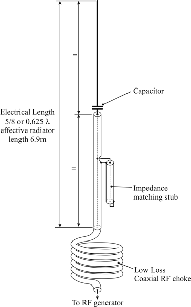
I am aware of several people who claim to have successfully made a Gainmaster clone using a 5 turn on 4.25 inch form choke. The "schematic" put out by Gainmaster simply calls for a "low loss coaxial RF choke", here is the "schematic" as it exists on their site. How many turns does it show for said choke? (answer 5.5 turns of an unknown diameter)

If you like, when I get some time, I can create models showing a given antenna with chokes at different parts of the antenna, and wherever the choke is you will see a corresponding current minimum, which by definition is also a voltage maximum.
It is always a pleasure to talk to you Homer.
The DB
