• You can now help support WorldwideDX when you shop on Amazon at no additional cost to you! Simply follow this Shop on Amazon link first and a portion of any purchase is sent to WorldwideDX to help with site costs.
  • Click here to find out how to win free radios from Retevis!

Browning Golden Eagle Mark III arcing plate tune cap

K

Kachina

Guest
Hello,
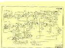
I'm not new to tube gear but I'm new to these radios. I got the receiver working but when I went to try to key up the transmitter I got arcing on the tuning cap. I thought maybe it was just out of tune at first but it was arcing no matter what I did. Then after looking at the schematic it seemed I was missing some parts and that the final tube had been swapped out with a 6201.
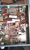
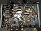
Because the 6201 is not a perfect match for the stock 7558 I figured maybe someone had modded the final section, but now I'm starting to think I'm just missing parts. Here is a photo of the final section that seems to be missing stuff.
Do I need to rebuild this whole section using the schematic, or what is going on here?
radio missing stuff.jpg
 

Here's what a stock one should look like underneath
 

Attachments

  • 152993237_3009142265971202_5944416480952912182_n.jpg
    152993237_3009142265971202_5944416480952912182_n.jpg
    281.3 KB · Views: 8
  • All original MK III Txer .jpg
    All original MK III Txer .jpg
    450.1 KB · Views: 8
  • Like
Reactions: Kachina
First thing I would do is try a 7558. The tube in there is a 12at7 which is in no way a final for that radio. Someone probably just stuck it in there. Looks like it's an early transmitter without the alc circuit. Also someone changed out the small variable cap on the tube for a larger one. That is to set the bias.
 
First thing I would do is try a 7558. The tube in there is a 12at7 which is in no way a final for that radio. Someone probably just stuck it in there. Looks like it's an early transmitter without the alc circuit. Also someone changed out the small variable cap on the tube for a larger one. That is to set the bias.
Thanks for the replies guys.

I just got a 7558 delivered and popped it in. The arcing has stopped. I have some other issues now that I think may get resolved when I swap out some of these electrolytic caps (lots of noise on transmit when I'm not talking into the mic - when I do talk it seems to modulate normally, but when I just key down the station monitor shows a noisy waveform instead of a solid carrier).

in terms of that variable cap that's coming off the final tube and going to the transformer can that has been modified from the original. You mentioned it was for bias, but I have a bias adjustment on the rear of the chassis. Can you explain how the internal one needs to be dialed in?

Also, it seems I'm still missing some circuitry that appears on the schematic and photos, including that potentiometer that appears in the pics posted by tramd (thanks). Do I have an earlier version, or am I missing stuff? Is there a schematic available somewhere for the earlier version?

Another problem with this rig is the needle on the meter is snapped off. There's maybe just enough of a nub remaining that will allow me try to reattach it if it's still inside the meter casing. I'll look for it when I take it apart and try some jb weld or something. Meters for these dont seem easy to come by.
My mistake. I meant to say it is for neutralization. It's to neutralize the final. Early sets had this. Later sets did not. As far as noise on transmit. Did you try just jumping pins on mic jack to rule out dirty contacts? If so check the tube sockets. Then check the 6bq5 by tapping on it lightly and see if the sound changes. Might be microphonic. Do you get the same static on SSB? As far as needle on meter. Is the back of the meter black, white, or clear? I might have one depending. Also if it snapped off it could be for 2 different reasons. The lesser would be someone had it in the Modulation position and just had it slapping over too much. The worse of the 2 would be a bad mode switch which sends high voltage to the meter and pegs it. That would also explain the noise on the carrier. Shut all the light off and make your room dark. Watch the mode switch on the back side. Look for tiny lightning bolts/arcing. If you see any you need a mode switch. The replacement switches were made of ceramic. The original were bakelite that breaks down and sends HV across points it should not. If it needs a mode switch I have those. The better ceramic replacement.
 
Last edited:
  • Like
Reactions: Kachina
My mistake. I meant to say it is for neutralization. It's to neutralize the final. Early sets had this. Later sets did not. As far as noise on transmit. Did you try just jumping pins on mic jack to rule out dirty contacts? If so check the tube sockets. Then check the 6bq5 by tapping on it lightly and see if the sound changes. Might be microphonic. Do you get the same static on SSB? As far as needle on meter. Is the back of the meter black, white, or clear? I might have one depending. Also if it snapped off it could be for 2 different reasons. The lesser would be someone had it in the Modulation position and just had it slapping over too much. The worse of the 2 would be a bad mode switch which sends high voltage to the meter and pegs it. That would also explain the noise on the carrier. Shut all the light off and make your room dark. Watch the mode switch on the back side. Look for tiny lightning bolts/arcing. If you see any you need a mode switch. The replacement switches were made of ceramic. The original were bakelite that breaks down and sends HV across points it should not. If it needs a mode switch I have those. The better ceramic replacement.
Thanks for the help.

I got a copy of Sam's photofact to help identify some things and it looks like it's the ALC circuit that was missing near the final - which I think you mentioned the older versions didn't have, so nothing critical.

It also means my older version is going to have a different schematic I hope I can track down in case there are other differences.

I will check out the mode switch and other tests, thanks for those recommendations, I think it's possible it is the mode switch because I haven't actually been able to get any output on SSB yet. However, the issue seems to be related to heat also. If I key up before it's had a chance to fully warm up, I get a clean looking carrier. But if I hold the key down the noise slowly appears and remains until I power it down and let it cool again. One thought I had is maybe the silver mica cap on the tuning cap is suffering from "silver mica disease." I ordered a new one just in case.

The meter I have has a clear back, not sure if that's the kind you have. I haven't taken it apart yet.

Thanks again, I'll be working on it more today
 
  • Like
Reactions: Tech5
OK, here is an update:

All the electrolytics are replaced. I changed out that silver mica with a similar value mica I had laying around while I wait for the replacement. I cleaned all the tube sockets (I previously tested all the tubes and they all tested around 100).

I'm having the same issue. tapping and wiggling the 6bq5 seems to have no effect on the waveform. I don't see any arcing on the mode switch wafers.

Something that is now different is I now seem to get full carrier on both lower and upper sideband, I'm almost positive I wasn't getting any output before - the waveform is clean on the SSB carrier, and remains that way even after warm up. However, I get NO modulation at all on SSB when I talk in the mic, and I never have.

On AM the problem is exactly the same as before. I get the carrier looking normal and normal modulation when I speak into the mic. However this only lasts a few seconds before the carrier begins to break down.

I took some pictures so you can see how the waveform breaks down.
aphoto_2024-07-26_17-02-42.jpg

Note: Even when the carrier is in full breakdown (the 3rd picture) If I grab the mic and yell into it, I can see that my voice is being modulated and it over powers the noise until I stop talking then it goes right back to the noisy waveform.
 
The most-common thing to go first in the mode selector is the meter section. It develops a leakage path to an adjacent lug that goes to a switch circuit on the opposite side of that wafer. A few hundred Volts starts leaking into the meter selector switch. Makes the meter peg when the "Mod" position of the meter is selected. If you see this, pull the plug RIGHT NOW!

No need to fry the meter. There is a simple way to connect the Mod circuit of the meter switch directly to the AM modulator-voltage circuit bypassing the mode selector altogether. Doesn't fix the mode selector's downhill snowball, just serves to protect the meter.

The only way the mode selector could still be okay is in a radio with under 1000 original miles, and extremely clean. Any layer of schmoo on the brown wafer material can develop leakage between adjacent rivets on the switch wafer. They really are very close together.

When someone says the electrolytics have been changed in this model, I often find the small ones are still original, and only the big ones are new. The small caps must also go, every single electrolytic-type capacitor.

The mischief you're seeing sounds pretty equally like mode-selector trouble, dirty/oxidized tube sockets and failing low-voltage electrolytics. A tube can do this too, but will usually respond to being tapped and reveal itself that way.

73
 
Thanks for the info, I'll likely update the mode switch as well. I'm not sure that this is causing all the issues that I'm having right now with AM modulation, however it might be connected to the problem with the carrier with no modulation on SSB. Also I have replaced all the electrolytics, not just the filter caps. Even if they tested good, just in case.

As far as the meter goes, even thought the needle is knocked off, I can still see the nub and it rocks back and forth with modulation. As you said though, probably need to swap out that mode switch soon anyway.

As for an update, I managed to get that noise to go away by cleaning out the mic gain pot R38. Before I could celebrate, however, I realized that my audio was still very distorted. I decided to try a new mic, so I took the 2 pin plug off the banana style mic it came with and put it on a turner 253 i had on the shelf. I had to bring the audio up using the mic gain pot R38, but it was still distorted.

This image shows what is being transmitted when I feed 1khz tone into the mic. The waveform seems to have a similar distorted shape no matter what the tone.

I see some of those ceramic wafers on ebay, is that the best place to get them?
The ones on ebay are only for the mode selector and not for the meter, is there another place to get them?

photo_2024-07-26_22-32-09.jpg
 
Last edited by a moderator:
Also, I noticed in your other post that you said you bypassed the mode switch entirely and made the transmitter AM only.

A. Do you have a post that describes how to do this?

B. Is it easy to reverse if I decide later I want the mode switch and SSB?

C. Does your post talking about moving the yellow wire make it so the meter is on modulation all the time, disabling the meter switch entirely?
 
Thanks for the replies guys.

I just got a 7558 delivered and popped it in. The arcing has stopped. I have some other issues now that I think may get resolved when I swap out some of these electrolytic caps (lots of noise on transmit when I'm not talking into the mic - when I do talk it seems to modulate normally, but when I just key down the station monitor shows a noisy waveform instead of a solid carrier).

in terms of that variable cap that's coming off the final tube and going to the transformer can that has been modified from the original. You mentioned it was for bias, but I have a bias adjustment on the rear of the chassis. Can you explain how the internal one needs to be dialed in?

Also, it seems I'm still missing some circuitry that appears on the schematic and photos, including that potentiometer that appears in the pics posted by tramd (thanks). Do I have an earlier version, or am I missing stuff? Is there a schematic available somewhere for the earlier version?

Another problem with this rig is the needle on the meter is snapped off. There's maybe just enough of a nub remaining that will allow me try to reattach it if it's still inside the meter casing. I'll look for it when I take it apart and try some jb weld or something. Meters for these dont seem easy to come by.
Here is the schematic you need. The potentiometer that you are missing (R69) is part of the ALC circuit that the 1974 and later transmitters had. Also, the instructions you need are here on this site under:

CB Radio Modifications​


Attachments

  • Mark III SSB Transmitter.jpg
    Mark III SSB Transmitter.jpg
    1 MB · Views: 9
Last edited:
disabling the meter switch entirely?
Nope. The meter selector still has its other three functions. The only difference is that the "Mod" function came from two sources. One for AM only and one for SSB. The SSB side is a waste of time, and who needs a mod meter for sideband? Yeah. And that's all that gets disabled with this bypass, is the mod meter function in SSB mode.

And for a radio that no longer has sideband, not an issue.

Thought sure I had posted at least one of the two versions of the Mark 3 transmitter's mode-selector bypass. There are two version of the transmitter, first with no SSB ALC, and the post-1974 version that HAS a sideband limiter circuit are wired just differently enough to require two separate procedures.

I'll see if I can find the post. Must have been in the last ten years, anyway.

73
 
Last edited:
Last edited:
Here is the schematic you need. The potentiometer that you are missing (R69) is part of the ALC circuit that the 1974 and later transmitters had. Also, the instructions you need are here on this site under:

CB Radio Modifications​

Thanks for this! This transmitter was definately a golden screwdriver victim and I'm trying to undo the damage. I managed to fix a few caps and resistors that were the wrong value.

I still have the overmodulated noisy audio problem, would love to find a block diagram if one exists.

Also, I'm having trouble reading the value on this resistor R58. For some reason whoever was in here before replaced it with 2x 470k resistors in parallel, which needs to be fixed, but I can't tell if the schematic says 2.2k or 22k ?
Screenshot 2024-07-29 061158.png
 

dxChat
Help Users
  • No one is chatting at the moment.