Thanks, Shockwave for this answer. I appreciate it. Not too many in this thread so far.
I am asking sincere questions. In this part of the ARRL Antenna Handbook it speaks of a full 90° mobile antenna.
Is this not a 1/4ƛ whip?
Unless a case can be made for it not being a 1/4ƛ whip, there is a lot of credibility at stake here for the argument that a properly made center-coiled antenna can not result in improvement in performance over a 1/4ƛ whip.
I am one of those doing more reading than writing here, and I see a lot of arguing that leaves more questions unanswered from both sides of the debate than are answered. I really would like more than stuff like "everybody knows . . "., and " . . .widely accepted" kind if assumptive statements. Or will I, as in other places when someone asks for answers be arrogantly told to "get my learn on"?
If I am to derive any truth from this debate I'll need to have something more than taunting and put-downs to read.
If you're going to take the Draino from the baby, give him a safe toy in its place. . . and that is common sense practice among informed parents. . .
Thanks, everyone,
Homer
ARRL Antenna Handbook - ch 16
"The current varies with the cosine of
the height in electrical degrees at any point in the base
section. Therefore, the current flowing into the bottom
of the loading coil is less than the current flowing at the
base of the antenna.
But what about the current in the top section of the
antenna? The loading coil acts as the lumped constant
that it is, and disregarding losses and coil radiation, maintains
the same current flow throughout. As a result, the
current at the top of a high-Q coil is essentially the same
as that at the bottom of the coil. This is easily verified by
installing RF ammeters immediately above and below the
loading coil in a test antenna. Thus, the coil “forces” much
more current into the top section than would flow in the
equivalent section of a full 90º long antenna. This occurs
as a result of the extremely high voltage that appears at
the top of the loading coil. This higher current flow
results in more radiation than would occur from the
equivalent section of a quarter-wave antenna. (This is true
for conventional coils. However, radiation from long thin
coils allows coil current to decrease, as in helically wound
antennas.)
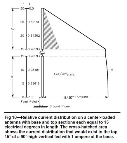
The cross-hatched area in Fig 10 shows the current
that would flow in the equivalent part of a 90º high
antenna, and reveals that the degree-ampere area of the
whip section of the short antenna is greatly increased as
a result of the modified current distribution. The current
flow in the top section decreases almost linearly to zero
at the top. This can be seen in Fig 10.
The degree-ampere area of Fig 10 is the sum of the
triangular area represented by the current distribution in
the top section, and the nearly trapezoidal current distribution
in the base section. Radiation from the coil is not
included in the degree-ampere area because it is small
and difficult to define. Any radiation from the coil can be
considered a bonus."