• You can now help support WorldwideDX when you shop on Amazon at no additional cost to you! Simply follow this Shop on Amazon link first and a portion of any purchase is sent to WorldwideDX to help with site costs.
  • Click here to find out how to win free radios from Retevis!

Cobra 2000 L38

Cable Guy

Packaged by weight, some settling may occur.
Dec 29, 2010
414
349
73
West Tennessee
Found above radio in a friend's shop, buried under random shop stuff, you know. He gave it to me, knowing I tinker with them. Sometimes I get blessed like that.

While looking over my new pet, I noticed L38 was missing his slug. I dropped one in and it immediately dropped power output. Peaks (falsely) with the slug out. Drops going in until about 2 turns from the bottom, then begins to climb some until it bottoms out. Hmmm, that ain't right but I am seeing a 3 watt dead key with approx 13 watts pep in AM.

Should I leave it alone or investigate? That is a loaded question, mind you.
 

Thanks, I have the Sam's for it, I aligned it okay, only small gain. 3.5dk\14 pep. I'm going to check the other parts of that 27mhz filter, maybe a cap has drifted, been changed, etc. I wonder if that is part of some mod, it doesn't look molested but I haven't hard-eyed the parts values and compared. Maybe someone has seen this before. My other C2k only does a few watts more, about 18 pep.
 
Check all the caps in the match/filter/trap network and visually inspect the coils to be sure nothing was swapped and the coils aren't spread out. If all that checks out, it may be the slug material or maybe even a badly stressed transistor. L38, based on what I have in simsmith. should be providing around 200nH.

A while back I had put all the components of a 2000GTL output section into simsmith to see what effects the adjustments had. However, for those tired of my ramblings cluttering up the threads, I will put the rest of that in a spoiler :D.

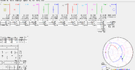
Power mods affect the transistors output impedance, and changing the DK will de-tune everything after it. For this example, I assumed the transistor had a 5Ω output impedance with factory settings and adjusted the coils to match based on the capacitor values given. That coil (L38) that once matched the 5Ω transistor impedance to the 50Ω filter network, will no longer match to 50Ω. Turning up the dead key may not release the magic smoke, but that is one thing that can knock down the sharpness of the L-match adjustment, because instead of passing through 50Ω, the path change caused by that adjustment is now further away from the center and not crossing it, but instead, more closely following a constant SWR path. Here is everything tuned for a 5Ω transistor impedance. The blue line is the effect of varying L38 from 180nH to 210nH.

L38 Sweep 5Ω.png

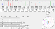
But lets say we mess with the output power (thus transistor impedance)? These next two are the effects of the same L38 adjustment with a 3Ω transistor and a 7Ω transistor:

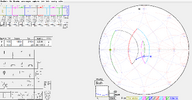
L38 Sweep 3Ω.png
L38 Sweep 7Ω.png

Notice how that adjustment now causes the adjustment to ride along the 2:1 SWR circle? This translates into less change in output power for a given tuning range.

Up to this point, I have excluded the harmonic trap because I have an issue with it ~ recall that I used the capacitor values from the schematic. For this part, I am back to the 5Ω transistor impedance and this time the blue line is sweeping the frequency response. Adding the harmonic trap de-tunes the network such that adjusting any of the inductors will not provide a match. Here is without the trap (horizontal blue line sweeping network response from 26-28MHz):

2000GTL Without trap.png

But if I then add the trap, this happens:
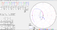
2000GTL with trap.png

Still within the 2:1 SWR circle, but again, this affects the response of the adjustments. As the big guy says, C'mon Man! And it seems the only way to correct that on the smith chart is to change the value of C141 from 82pF to 47pF. I have not tried this in practice, but I might as my current 148/stalker project has similarly insensitive adjustments on the back end.
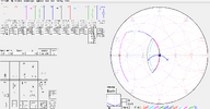
2000GTL adjusted for trap.png

Is it worth chasing absolute perfection making these adjustments do exactly as they were intended, probably not.. But I find this stuff interesting and felt it was worth at least sharing.
 
Thanks, I will check the output network after work today. That simsmith is fascinating and I will get that too. I thought about connecting the network to the nanovna and figuring what it is doing and, thanks to you, I have some ideal data to check against.

This radio has a 2166/1969 combo, all looks untouched.

As for slug composition I used a slug from another c2k.
 
Brandon: I believe that's what R178 (10K 1/2 watt) in parallel with the trap on the original 148 is for, to compensate for the TVI trap. (R414 on the 2000). On all of the newer front mic 148's, C141 is changed to 47pf and the 10K is omitted.
 
  • Wow
Reactions: lonestarbandit
Brandon: I believe that's what R178 (10K 1/2 watt) in parallel with the trap on the original 148 is for, to compensate for the TVI trap. (R414 on the 2000). On all of the newer front mic 148's, C141 is changed to 47pf and the 10K is omitted.
The 10k is to dissipate static charge on the antenna/coax. Wind blowing across an antenna that is isolated from DC ground can generate thousands of volts every second which the coax (acting as a capacitor) stores up until it arcs over somewhere. The resistor keeps that charge from ever building up to the point it could hurt anything.

Resistors move things along the constant susceptance curves, so a resistor of any value in that spot could not correct for the effects of the trap, and a value that high wouldn't move that plot noticeably anyhow.

Thanks for pointing out that somewhere along the line they did switch to a 47pF cap, good to have a sanity check once in a while!
 
  • Like
Reactions: Cable Guy
This one has the 82pF cap as c141. All caps, 141,142,143,146,147,148 match the Sam's, and tests to within spec. C149 calls for 120pF but this one has a 100pF. C150 calls for 330pF, this a 470pF. I haven't checked the inductors yet.
 
This one has the 82pF cap as c141. All caps, 141,142,143,146,147,148 match the Sam's, and tests to within spec. C149 calls for 120pF but this one has a 100pF. C150 calls for 330pF, this a 470pF. I haven't checked the inductors yet.
I believe the mystery is solved then. Although changing C149 that much has little effect, changing C150 to 470pF has a profound effect. I assume someone thought "less capacitive reactance, more gets through". That is not true with tuned circuits.

If I change the value of C150 to 470pF, the plot looks like this:

C150 1.png

With that capacitor wrong, lets see what happens if we go back and vary L38 from 180nH to 210nH again:

C150 2.png

And what do ya know!!! The lower the inductance, the closer to 50Ω! That right there is why it gets more power through the L-match with the slug removed!

Change C149 and C150 back to the schematic values, and while you are in there, swap out C141, then give that adjustment another try.
 
  • Like
Reactions: 999 and Cable Guy
I will give it a try. That makes sense, and your explanations and graphical aides are most helpful. I will update tomorrow, thanks again!

Edit: I may have to order unless I can salvage that value from the pile.
 
Last edited:
  • Like
Reactions: brandon7861 and 999
One last little bit before you dive into this... I think Cobra did the same thing I did when designing the radio, called the transistor 5+j0 and hit GO. If I enter the conjugate of the transistor output impedance as listed in the old Mitsubishi datasheet, C150 drops from 330pF to 270pF and C146 also goes down from 390pF to 330pF. C141 becomes 55pF instead of 47pF. The two air-wound filter coils remained constant at 284nH. Good Luck!!!

final thoughts.png
 
  • Like
Reactions: Cable Guy
This is interesting, but i can't imagine how that value 470puff got there. It would seem whoever did it would know it wasn't right, with the loss of output and having to remove the slug from L38 to regain a bit.
Okay, I can see someone blindly following some mod, but the quality of soldering was not indicative of that, it really looked factory soldered, if you know what I mean. I've seen too many hack jobs of people following some mod found scribbled on the bathroom stall. In most all instances, the soldering skill was the tip-off.
 
Could be it got mixed up at the factory, or perhaps the "tech" before actually used flux and had a eutectic solder that is guaranteed to solidify nice and shiny.

In playing around with the sim, increasing C150 always corresponds to a drop in the value required of L38 (and a decrease in Q of the overall circuit). So I don't think there is any harm in attempting to swap out that cap with a lower value, even in the absence of evidence that it was attacked with a soldering iron.

If there is anything to be taken from the vast number of technical bulletins out there, its that nobody is perfect, Cobra included.
 
  • Like
Reactions: Cable Guy
Now I am wondering something else, but it's a little off the main topic...

If I go back to the schematic values exactly and use the 5+j0 "estimate" for the transistor rather than the specific impedance of the 1969, the antenna jack goes reasonably capacitive in the sim. I imagine with a physically short mobile whip that is already capacitive, achieving a 1:1 flat match would be quite difficult ~ if not impossible. And there seems to be no shortage of people with that very same problem! But now I am going way off course, lots of theories and not enough actual testing. I'll shut up now :)
 
  • Wow
Reactions: Cable Guy

dxChat
Help Users
  • No one is chatting at the moment.