• You can now help support WorldwideDX when you shop on Amazon at no additional cost to you! Simply follow this Shop on Amazon link first and a portion of any purchase is sent to WorldwideDX to help with site costs.
  • Click here to find out how to win free radios from Retevis!

Cobra 29 T1 transformer specifications

350GA

Member
Oct 14, 2018
36
21
18
35
Good evening everyone!

I'm working on a project Cobra 29, messing up around with direct injection, and so far it's working flawlessly! Super smooth audio with my rack gear!

I've been digging around and doing some research looking for a suitable upgrade for audio transformer T1. I found some Hammond audio transformers , but I'm not exactly sure on which one to select, and the ones I've price checked are around $70-$80 each, so not much room for buying several to try out. Lol https://www.hammfg.com/electronics/transformers/audio

I did find this old catalog that listed the specs for a TF-129-A with 20k primary and 600/250 ohms secondary impeadance and this seems like it might be correct, but would like to get one of the 20Hz-20KHz Hammond transformers to extend the frequency response range if any of theirs will work for this.

Any ideas on which one to go with or any other suggestions? Thanks!
 

Attachments

  • Screenshot_20201123-204857.png
    Screenshot_20201123-204857.png
    1.9 MB · Views: 15

You can't simply "strap in a coil" - you're lower Line to Voice coils series is the ones you need to look at.

Because of the Line input - your TF-129 rating is in mA and maybe 1 amp draw - and needs the Line to Audio multi-tap impedance match approach.

The output of the TF-129 is ISOLATED speaker coil wind - so it's more of an Isolation type than a Line to Audio transformer tap.

The TF-129 works the way it does because of how the winds are "flipped" on the board - the output wind simply goes to the cap side of the Audio out, the Line winds are less - but carry the current - the last tap - the 3rd leg is where the audio or "auto-transformer" effect takes place.

Other radios use the Multi-tap approach to handle the current draw - but again suffer the fate of the DC to AC + Bias conversion and the inherited frequency response losses.
 
Thanks guys! I really appreciate the responses!

Shadetree, if you happen to run across that thread, I'd definitely be interested in reading up on that. Thank you!
 
ditching the transformer and using a Darlington pair to modulate with. Like what the 148 uses.

You'll sacrifice over half the peak power you get from the transformer. It puts 24-Volt plus audio peaks onto the final's collector. The darlington/148 solution half that or less.

Would work, but wattmeter worshippers will hate it.

73
 
Haha I hear ya Nomad. Nah I'm not one of those guys. I'd rather have that smooth sound and let the amplifiers do the work.

I currently have it setup with 3w carrier peaking 12.5w and 5.5w of forward average as measured on my Bird setup. So I've got my roughly 1:4 ratio from the radio, going into a pair of 1446's keying 50w, peaking 200w, then into a single 8877 keying roughly 500w peaking at 2kw. It all just seemed to flow perfectly with this setup! I'm planning on getting a 3CX5000 built in the spring.

I just really would like to get a little more bottom end through the radio. I did change C48 to a 1000uf electrolytic, and that made a very noticeable difference.
 
  • Like
Reactions: Shadetree Mechanic
the darlington mod you speak of was drawn up by Reverand Bow.
Good guy and knows his stuff.

here is a diagram of what he made:
bmedarlingtonmodulator1-1-jpg.39003


know that peak power will be pretty significantly reduced.
There are drawbacks to removing the transformer from the equation.
I've done it and it does work, but really unless you are doing direct injection there is no reason to do it.
sounds like you are, so it might be what you are looking for.
LC
 
  • Like
Reactions: Shadetree Mechanic
Hi, have a good one.

I've made some amateur repairs and it's a charm to be doing this and I've been silently taking a lot of good tips from you guys.

Do anybody has info about how to replace the transformer with transistors? I mean I've read some times that you can use a Darlington array to better the audio quality (in my case I have a Cobra29 my father gave me some years ago)

I need to use that mod but I've not been able to find it

Thanks a lot, beforehand
 
So here is your problem. The transformer boosts the audio voltage from about 12 Volts peak-to-peak up to about twice that, 24 Volts peak to peak or more. One end of the step-up secondary winding has the 12 Volt DC power supply feeding into it. What comes out the other end of that winding is that 12 Volts DC with 24 Volts of peak audio riding "piggyback" along it. The audio waveform goes down to zero and up to 24 Volts or more on audio peaks. The collector circuits of the driver and final now get a peak audio voltage of 24 Volts or more. There's no easy way to do this without a transformer. There are some not-easy ways. The Motor Mouth Mauldulator does it by using a 24 Volt DC power source, and simulating the modulated DC voltage the transformer would provide to the driver and final.

I suppose you could take a 12-Volt to 24-Volt DC-to-DC switchmode converter powered from the radio's DC source and feed the 24 Volts DC into a Mauldulator. That would get rid of the transformer.

There was (or may still be) a solution called the asymod that combined the DC-to-DC step-up and a modulator circuit similar to the Mauldulator all on one circuit board.

But if you have a less-fanatical way to do this, please share.

73
 
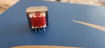
Cool thread. We've been experimenting with different laminents for the Cobra 29 modulation trasformer. The one pictured is a nickel core version. Although the lams are smaller than stock ones, they are actually heavier.

It's sounds quite a bit better than the stock version and with the Goldfinger audio mods it's tonality really shines.

I tried to explain this to my wife and I didn't
get the reaction I desired from the blessed event. So, I politely asked her to not swim in the pond
as I'm having a devil of a time getting the smell out of the fish....
 

Attachments

  • 20240926_131539.jpg
    20240926_131539.jpg
    2.1 MB · Views: 3
  • 20240926_131529.jpg
    20240926_131529.jpg
    1.9 MB · Views: 3
  • 20240926_131507.jpg
    20240926_131507.jpg
    2.5 MB · Views: 3
I tried to explain this to my wife and I didn't
get the reaction I desired from the blessed event.
Welcome to my world, of blank stares and drifting attention away from my cb forum life. She gets the same reaction from me too when she shows me pictures of goat buttholes from her goat forum life. Different strokes.
 
"HiFi" for a more robust, and rich sound!
Shout out to Rev Bow, for the BME thread + schematic, shout out to CBPhreaker for the Wabi-Sabi mod. (Darlington Pair)

Nomad is correct, without "rebuilding" the RF section around the decrease in voltage the radio output = QRP.

If one wanted to go through the trouble of doing this, they could get 4W to 16WPEP with 13.8V, and HiFi audio.

Strapping a laptop to the CB, tx/rx switching, and having decreased power output turns most people away from doing the mod.

With a higher voltage going to the collectors you can get more power, but most people have a single, fixed supply.

I think BlackPearlRadio557 has the right idea, solves the voltage issue while giving the radio a wider range of audio response.
 
Last edited:
Hi, have a good one.

I've made some amateur repairs and it's a charm to be doing this and I've been silently taking a lot of good tips from you guys.

Do anybody has info about how to replace the transformer with transistors? I mean I've read some times that you can use a Darlington array to better the audio quality (in my case I have a Cobra29 my father gave me some years ago)

I need to use that mod but I've not been able to find it

Thanks a lot, beforehand

um, look two posts above your original post.
that is the mod you are looking for.
LC
 

dxChat
Help Users
  • No one is chatting at the moment.