• You can now help support WorldwideDX when you shop on Amazon at no additional cost to you! Simply follow this Shop on Amazon link first and a portion of any purchase is sent to WorldwideDX to help with site costs.
  • Click here to find out how to win free radios from Retevis!

CRT Hercule display board

Tech5

Active Member
Jun 24, 2023
32
27
28
Sweden near the Arctic Circle
Hi and first post here!

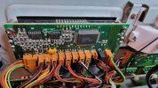
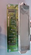
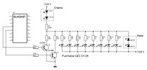
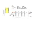
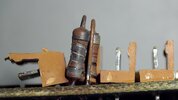
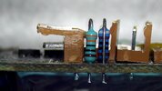
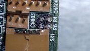
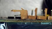
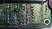
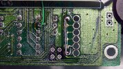
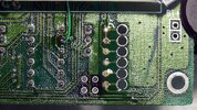
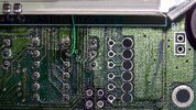
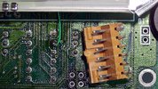
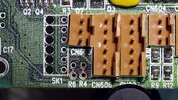
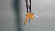
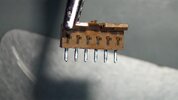
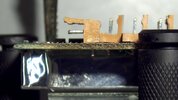
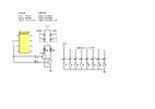
I have a CRT Hercule on my workbench that has had the display slightly modified. Someone has replaced the background illumination from the original light bulbs to leds, but it does not work as intended. I found a service manual on the web but the display schematic is not the same. By chance, does anyone have or know if there are several models of the display board?

Thanks in advance!
 

Attachments

  • Display PCB.jpg
    Display PCB.jpg
    2.1 MB · Views: 14

I think there are several clones of the radio built by Ranger, the Galaxy Saturn Turbo, 2990, 2995dx
What is the main board number on the radio?
I don't know if all the displays are the same on different production runs.
Chris ( Nomad) is well versed on these radios and the different models, if anyone knows what service manual might work I bet he does.
Welcome to the forum.

73
Jeff
 
  • Like
Reactions: Tech5
Thank you for the reply and welcome Jeff! =)

There are two markings on the main board: 2994HB and EPT295013Z. I have only found one service manual but it does not match the driver transistors for the dimable back ground illumination, which is done – I think – in three steps, of the display. It would be much appreciated if someone could shed some light on this matter. The leds for the illumination flicker like a amusement park right now! =)

73
Bjorn
 
  • Like
Reactions: AudioShockwav
The dimmer circuit places one or both of two half-Watt resistors in series with the display's bulbs. A surface mount transistor on each of the two resistors selects one, the other or both resistors in parallel to get three brightness levels.

Just one problem. Those two resistors overheat. And if someone replaces the original bulbs with a higher-current type, those resistors will get cooked, along with the circuit board under them. Damaged resistors can make the display backlight flicker randomly.

I have just enough fear of damaging the surface-mount circuit board that we simply wire new LEDs to illuminate the display directly to the radio's DC power. You can no longer select brightness, but they won't flicker any more.

Consider also that those two resistors depend on the high current draw of the original bulbs to obtain the dimmer settings. LEDs don't draw enough current to get dimmed by the stock resistors. Haven't felt brave enough to try changing them to a higher resistance value correct for LEDs.

73
 
Thanks nomadradio for allo the valuable information!

Aha! On the Hercule schematic I have they use 4 transistors with different values for the collector resistors so with other words that is far from the two transistors you wrote about. I had a quick look at the display board and these two resistors get really hot and partly cooked.

Well … feed the leds fom the dc power 13,8 volts would certainly solve the problem, but if I do not find an easy solution with these leds I may use small light bulbs instead and also replace the two resistors. By the way, it seems that the switching for the instrumentation light uses anoter circuit to control the background illumination.

However, I measured the voltage after the last led, IE cathode side which goes to the resistors, and the voltage counting from step 1 to 3 was: 9,5v, 8,2v and 7,9v. What I noticed when I checked the voltage with my scope, when the leds where flickering, it first looked like it was pulse width modulated but it did not look like that, it was more as random pulses.

Nomadradio, do you by chance have schematic on this type of display?

73
 

Attachments

  • CRT Hercule illumination.jpg
    CRT Hercule illumination.jpg
    161.1 KB · Views: 9
  • Like
Reactions: AudioShockwav
Thank you nomadradio!

I took out the display board with the the DPT prefix which can be seen in the attached photo. I found the two transistors Q2, Q4 and the resistors R4 (82R) and R6 (56R). :)
 

Attachments

  • Displayboard 1.jpg
    Displayboard 1.jpg
    1.1 MB · Views: 8
  • Like
Reactions: AudioShockwav
Thank you so much nomadradio!

Yepp, that is the right schematic for this display. They wrongly placed PNP transistors in the schematic for the dim switching, which are NPN, but everything else is perfect as far as I can see. I will hook up the scope, just for fun, on the base on both transistors in order to see the base drive coming from the shift register.
Thanks again nomadradio! :)

73s

Bjorn
 
  • Like
Reactions: AudioShockwav
Hi again!

This is what I did to get the LED illumination for the display to work and will do just about the same with the meter LEDs as soon as I got time to do it. I may change values on the resistors R4 and R6 in order to get a bit better dim steps, but it would have been nice to have the LEDs PWM controlled. Thanks again nomadradio for the help with the display/CPU schematic!

73s
 

Attachments

  • Hercule CRT LED.jpg
    Hercule CRT LED.jpg
    192.1 KB · Views: 12
I thought I would share my dim mod with LEDs on the CRT Hercule display as well as the meter backlite. There is now three dim steps but they are not 100 percent okay because it is quite difficult to get it perfect with two resistors. Of course, if I would have spent more time it may have been close to perfect but found it to be acceptable. Attached are some photos on how I did it including a slight modification on the stupid 90 degree connector SK1.
 

Attachments

  • CRT Hercule mod.jpg
    CRT Hercule mod.jpg
    329.2 KB · Views: 10
  • 1.jpg
    1.jpg
    172 KB · Views: 11
  • 2.jpg
    2.jpg
    165.1 KB · Views: 10
  • 4.jpg
    4.jpg
    251.3 KB · Views: 9
  • 5.jpg
    5.jpg
    157 KB · Views: 9
  • 6.jpg
    6.jpg
    704.6 KB · Views: 8
  • 7.jpg
    7.jpg
    674.8 KB · Views: 8
  • 8.jpg
    8.jpg
    662.6 KB · Views: 8
  • 9.jpg
    9.jpg
    628.5 KB · Views: 8
  • 10.jpg
    10.jpg
    543.7 KB · Views: 8
  • 11.jpg
    11.jpg
    592.9 KB · Views: 8
  • 13.jpg
    13.jpg
    78.2 KB · Views: 12
  • 12.jpg
    12.jpg
    99.4 KB · Views: 9
  • 14.jpg
    14.jpg
    175.9 KB · Views: 11
This is how when I read something quick your mind pieces stuff together based on knowledge and experience. Reading quickly, the title. I thought he’s was talking about replacing a CRT Hercules board, the IBM PC Hercules Graphics Adapter. I’m thinking if your having issues I have one packed in Mylar bag. I’ll mail it to you. I thought someone was using the PCB and components in radio build. Anyway great work.
 
  • Like
Reactions: Tech5
Thank you so much secret squirrel and yes I know very well what you mean! Maybe it would have been wise to just start a new thread, but since I started here, also got lots of help, I thought It could not be that bad to add the mod. It is not an easy task to achieve dim steps with two resistors that the human eyes perceives perfect luminescent changes in three steps, but - as I wrote - found it to be acceptable and my friend who owns the radio was very happy and that is enough for me.

I should also have done as in my attached schematic for the reason that I find no need to dim the push buttons. It is not BTW the best way to parallel the two led strings, but it works just fine like that as long as the If (forward current) is kept within limit. :)

It is a rainy evening here close to the Arctic Circle so I will start another project but still have to find a service manual for this beauty (Royce 642) in the photo.
 

Attachments

  • CRT Hercule led mod pussh buttons.jpg
    CRT Hercule led mod pussh buttons.jpg
    333.3 KB · Views: 6
  • Royce 642.jpg
    Royce 642.jpg
    2.9 MB · Views: 6

dxChat
Help Users
  • No one is chatting at the moment.