• You can now help support WorldwideDX when you shop on Amazon at no additional cost to you! Simply follow this Shop on Amazon link first and a portion of any purchase is sent to WorldwideDX to help with site costs.
  • Click here to find out how to win free radios from Retevis!

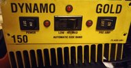
Dynamo Gold 150 (dual MRF455) Schematic needed

Rogerbird1

Well-Known Member
Apr 24, 2002
524
122
53
Massachusetts
rogerbird.tripod.com
I have seen someone post this model before, so it cannot be a totally obscure amp.
I feel it is a classic dual MRF455 type amp, so really any schematic with that transistor set will probably be close enough.

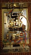
This amp has no output, the MRF455's seem ok. Nothing is visually burnt.
It was working till the owner used it on his beefed up HR2510, on SSB.
The 2510 has probably 35 to 45w SSB out. It was too much for this poor 150.

I am just trying to get it going again.

Thanks,
 

Attachments

  • dynamogold150 1.jpg
    dynamogold150 1.jpg
    190.7 KB · Views: 228
  • dynamogold150 2.jpg
    dynamogold150 2.jpg
    87.1 KB · Views: 235
  • Like
Reactions: Cabover Bob

cbtricks does not seem to have a similar schematic that i can find.

may be a bit pedestrian to ask you these, but does the relay click when keying the amp?
can you key through it with the amp off?

how did you test those 455's? the solder looks factory.
LC
 
The usual 10-ohm half-Watt "smoke" resistors from base to emitter look okay. And they're 18 ohms, not ten. When that type transistor shorts from collector to base, that resistor gets hammered. Not the only way for a MRF455 to fail. For that matter, I think the japanese-type transistors acted that way more than Motorola parts. Seems to me we have seen more than enough MRF455 that failed as an open circuit, not a C-E short.

Maybe. Until you unhook the base terminal from the pcb at the very least the condition of a MRF455 is an open question. That way you can see if junction continuity has been broken or shorted between base and collector, then between base and emitter. If either transistor is damaged, you probably won't need to unhook either C or E to get a go/no-go result. We don't care about measuring gain, just to see the forward and reverse "diode test" from a multimeter. And taking just the one leg loose reduces the chance of damaging the part.

And if those tests are okay, you wasted a lot less trouble than to remove them entirely for testing.

Oh, and this design reminds me of a "Boomer 250". Now to figure out if we ever had a diagram.

73
 
Last edited:
cbtricks does not seem to have a similar schematic that i can find.

may be a bit pedestrian to ask you these, but does the relay click when keying the amp?
can you key through it with the amp off?

how did you test those 455's? the solder looks factory.
LC
Yes the relay does click and it does pass tx when off. The Mrf455s have the switching voltage on the base. I will have to pull the Base (s) and make measurements.
 
The usual 10-ohm half-Watt "smoke" resistors from base to emitter look okay. And they're 18 ohms, not ten. When that type transistor shorts from collector to base, that resistor gets hammered. Not the only way for a MRF455 to fail. For that matter, I think the japanese-type transistors acted that way more than Motorola parts. Seems to me we have seen more than enough MRF455 that failed as an open circuit, not a C-E short.

Maybe. Until you unhook the base terminal from the pcb at the very least the condition of a MRF455 is an open question. That way you can see if junction continuity has been broken or shorted between base and collector, then between base and emitter. If either transistor is damaged, you probably won't need to unhook either C or E to get a go/no-go result. We don't care about measuring gain, just to see the forward and reverse "diode test" from a multimeter. And taking just the one leg loose reduces the chance of damaging the part.

And if those tests are okay, you wasted a lot less trouble than to remove them entirely for testing.

Oh, and this design reminds me of a "Boomer 250". Now to figure out if we ever had a diagram.

73
Yes, I will have to pull the bases to make the measurements on the finals. Nothing looks burnt, nothing is getting hot. it does pass TX when off. it does move the wattmeter needle slightly when keyed.. (not even miliwatts) just minor deflection of the needle. The Boomer250 does look close. C1 is a 24pf but it also has (I think a 68pf across C1) C1 is a small disc the 68pf is a kidney bean.. both appear to be stock.
 
I have seen someone post this model before, so it cannot be a totally obscure amp.
I feel it is a classic dual MRF455 type amp, so really any schematic with that transistor set will probably be close enough.

This amp has no output, the MRF455's seem ok. Nothing is visually burnt.
It was working till the owner used it on his beefed up HR2510, on SSB.
The 2510 has probably 35 to 45w SSB out. It was too much for this poor 150.

I am just trying to get it going again.

Thanks,
What about this one?
Pride 150 amp schematic.jpg
 
Hey Rogerbird do you plan on replacing the finals and repairing it?

If not I'd be interested in it as it is.

Adam
 

dxChat
Help Users
  • No one is chatting at the moment.