You are using an out of date browser. It may not display this or other websites correctly.
You should upgrade or use an alternative browser.
You should upgrade or use an alternative browser.
-
You can now help support WorldwideDX when you shop on Amazon at no additional cost to you! Simply follow this Shop on Amazon link first and a portion of any purchase is sent to WorldwideDX to help with site costs.
Electronic component identification help please
- Thread starter Danzik
- Start date
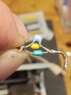
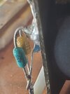
272 = 2700pF, 103 = .01uF, 104 = .1uF the look like monolithic ceramics, probably high voltage, like 500v or more.
Read my edit in post 5. Sorry for the mixup, SuperLid got it right..Anyone have a recommendation on what ones I should replace the capacitors with, would one cap be sufficient or not ? These are mostly just for filtering out noise arnt they ? Thank you guys for the help
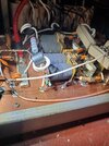
They are connected from the 12-Volt (?) power to ground, at the center-tap point of each push-pull output transformer. Textbook name for this would be "decoupling", or just "bypassing" capacitors. They keep the RF from leaking upstream into the power supply.
This is a strategy to filter harmonic frequencies as well as the 27 MHz RF energy. Putting three capacitors in parallel with widely different capacitance ratings becomes a wider-band RF filter than a single capacitor can deliver.
The larger capacitance values become less effective above 27 MHz. The smaller value caps are more effective for harmonic frequencies 54, 81, 108 MHz and up.
If they get hot and burn up, a larger component is called for. It's all about the capacitor's resistance. Bigger cap has more metal in it. More metal means lower resistance. Easiest way to do this with ceramic capacitors is a higher voltage rating. Naturally, a 12-Volt circuit doesn't "need" a 1000 or 2000 Volt cap. But those parts will be physically larger. Larger means more metal. More metal means lower resistance.
73
Last edited:
They are connected from the 12-Volt (?) power to ground, at the center-tap point of each push-pull output transformer. Textbook name for this would be "decoupling", or just "bypassing" capacitors. They keep the RF from leaking upstream into the power supply.
This is a strategy to filter harmonic frequencies as well as the 27 MHz RF energy. Putting three capacitors in parallel with widely different capacitance ratings becomes a wider-band RF filter than a single capacitor can deliver.
The larger capacitance values become less effective above 27 MHz. The smaller value caps are more effective for harmonic frequencies 54, 81, 108 MHz and up.
If they get hot and burn up, a larger component is called for. It's all about the capacitor's resistance. Bigger cap has more metal in it. More metal means lower resistance. Easiest way to do this with ceramic capacitors is a higher voltage rating. Naturally, a 12-Volt circuit doesn't "need" a 1000 or 2000 Volt cap. But those parts will be physically larger. Larger means more metal. More metal means lower resistance.
Thank you for the explanation of this Nomadradio, that described that perfectly! This whole situation began when a 2879 transistor went south, along with the 10 ohm resistor of coarse, and apparently took these caps out right along with it .


