I am told that I have an RF issue in my setup that is causing clipping, distortion and generally a difficult to understand signal even when running low boost or even no boost. I vaguely know in general what it is but to be honest I do not know the proper/methodical way to problem solve this one. I work as a data/BI engineer and while it is a technical profession, the skills are not exactly helpful here.
I have been running between 5 and 8 watts into the KL503HD, radio modulation set between 22 and 30, Zetagi mic modulation between 5 and 8 and the KL503HD anywhere from 1 to 6. I do get decent dead key from the amp given the varying power I put into it.
Here is the setup I have and all of it is new within the past few months:
Anytone AT-5555N II (purchased from and tuned by Scott's Radios, A+ vendor by the way)
Zetagi MB+5 mic and a stock Anytone mic
RM Italy KL503HD
RM Italy 27/586 low pass filter
Powermax PM4-120 power supply
MFJ-941E Versa Tuner II (antenna tuner)
Micronta SWR/Power tester
50 ft of RG213 coax from tuner to MFJ 272, 1.5 KW Lightning Surge Protector (connected to 8 foot copper ground rod)
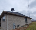
35 ft of RG213 coax from Lightning Surge Protector to Maco V58 antenna mounted 30 feet in air.
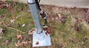
The mast holding the antenna is grounded to a second 8 foot copper ground rod.
New RG8X coax patch cords 1-2 feet long.
There are 3 foot long, 4 gauge stranded cables going from the PSU to a 150 amp bus. The radio and amp both pull power from this bus with the amp using 6 gauge cable and the Q5N2 using what came with it.
Here is the sequence in which I have the items connected:
Anytone AT5555N II radio.
RG8X patch cable from radio to Micronta SWR power tester (so I can tell in general how much power I am putting into the KL503HD)
RG8X patch cable from Micronta to KL503HD
RG8X patch cable from KL503HD to RM Italy 27/586 low pass filter
RG8X patch cable from low pass filter to MFJ-941E Versa Tuner II
50' of RG213 coax from antenna tuner to Lightning Surge Protector
35' of RG213 coax from Lightning Surge Protector to Maco V58 antenna.
I do not currently have a ground cable connected from the PSU chassis to a house ground or any other ground.
I have checked that all the coax connections are tight, except for the one at the antenna base. That'll have to wait until spring and the snow is gone.
Should I just start with a basic setup of antenna connected directly to the radio? I would at least temporarily have a meter in there to make sure the SWR is safe. Or is there a generally-accepted best practice for working through this type of issue?
I do enjoy all of the learning I have been doing here since I re-joined the hobby but I am also looking forward to when I can start paying some of it back.


