Im cleaning up a old cobra 29gtl i picked up that seems to work really well. It has 4 pin mic jack. Im yrying to use my d104 desk mic which is wired for 4 pin and works on my galaxy949 and 2950dx (with adaptor). Does it need to be wired differently for the older 4 pin cobra? Also what baffles me is the stock galaxy 4 pin mic works on the cobra, just not the d104. Its like there is no mic plugged in when i try it.

-
You can now help support WorldwideDX when you shop on Amazon at no additional cost to you! Simply follow this Shop on Amazon link first and a portion of any purchase is sent to WorldwideDX to help with site costs.
-
The Feb 2025 Radioddity Giveaway Results are In! Click Here to see who won!
Is there a difference in the old cobra 4 pin and new 4 pin?
- Thread starter cjruger
- Start date
the cobra radio needs pin 4 hooked up for receive,, the d104 probly doesn't have the pin 4 wired in to make the radio receive,, most other 4 pin radio's don't need the pin 4 so lots of times if someone changes the plug they don't even bother to hook up pin 4
So if i attack pin 4 on d104, will it affect
The other 4 pins that dont require it?
not usually,, some export 4 pin use the pin 4 for channel up down and may have voltage on that pin, but the radio's that you have now will all be fine with pin 4 wired for receive like the cobra needs
Thanks for the help, now i just have to figure out how to do it. There is a schematic on the inside of the base plate so hopefully tonight when i get home i can figure it out.
yes the diagram will show you what wire you need for pin 4, get out your test meter, you should have continuity on pins 1 and 3 when the ptt button is pushed and continuity on pins 1 and 4 when your not pushing the ptt button
Ok i opened it up but not sure what to do. This is not nearly as easy asi thought it would be. There is no continuity between 1&3 with ptt button held in. And none between 1&4 either. Im lost. It does seemed to be wired right to the diagram on the plate.


make sure your meter is working correctly,, and making contact with the mic connector pins,, if you said the d104 is working on the other radio's and has a 4 pin connector on it now you have to have continuity on pins 1 and 3 for the ptt button to work when pressed ,, also make sure your looking at the connector the right way to know for sure your probing the correct pins
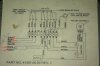
this is what you should have according to your wiring diagram:
pin 1 = blue + shield (ground)
pin 2 = white (audio)
pin 3 = red (ptt, transmit)
pin 4 = black (receive ground)
this is what you should have according to your wiring diagram:
pin 1 = blue + shield (ground)
pin 2 = white (audio)
pin 3 = red (ptt, transmit)
pin 4 = black (receive ground)
This is going by the numbers on the plug. If the little cut out is up., 1 is top right, 2 bottom right, 3 bottom left, 4 top left. This is what it is
1. White
2. Black ground ( to frame not neg on battery)
3. Red
4. Blue
Also how from the diagram do you match the colors with pin numbers? I do have continuity between white and red, they just are not matching the numbers on plug.
Eta: there is the continuity between the proper colors you stated when ppt is held and the blue and ground, its just they are not in the proper holes, so i should move them around to match your 1-4 you listed?
Last edited:

dxChat
- No one is chatting at the moment.
-
-
@ BJ radionut:
ARRL DX
The American Radio Relay League (ARRL) is the national association for amateur radio, connecting hams around the U.S. with news, information and resources.www.arrl.org
-
-
-