You are using an out of date browser. It may not display this or other websites correctly.
You should upgrade or use an alternative browser.
You should upgrade or use an alternative browser.
-
You can now help support WorldwideDX when you shop on Amazon at no additional cost to you! Simply follow this Shop on Amazon link first and a portion of any purchase is sent to WorldwideDX to help with site costs.
Locking the Clarifier on a 1st Gen 2970
- Thread starter Xjeepguy
- Start date
The USB is on frequency when the Clar is at 11 AM and LSB its on frequency when its at 1 PM . I don't mind that its unlocked so much as it not being centered on each sideband. I could probably save a bunch of work , center it and re-adjust L19 and L20 ?Wouldn't just putting it at 12:00 solve the problem?
Last edited:
That's what I was looking for, hey that's much appreciated, thanks.
73, Jeff 102 BC
Yes.. I could probably save a bunch of work , center it and re-adjust L19 and L20 ?
73
Jeff
That sounds to me like it was aligned to spec. USB is supposed to be 1.5kc up and LSB is supposed to be 1.5kc down, but that's not how CBer's run. They want it on the zero, no matter what.The USB is on frequency when the Clar is at 11 AM and LSB its on frequency when its at 1 PM . I don't mind that its unlocked so much as it not being centered on each sideband. I could probably save a bunch of work , center it and re-adjust L19 and L20 ?
The mode selector also informs the computer running the show which mode you are in. It should instruct the PLL to offset the VCO frequency the correct amount to keep all three modes centered at 12 o'clock. But only if all three oscillators in the radio are on frequency.
73
73
Possibly yes .That sounds to me like it was aligned to spec. USB is supposed to be 1.5kc up and LSB is supposed to be 1.5kc down, but that's not how CBer's run. They want it on the zero, no matter what.
I'm going to set the CL to 12 and tune the two slugs . While I'm in there I'm going to install the relay I got from youThe mode selector also informs the computer running the show which mode you are in. It should instruct the PLL to offset the VCO frequency the correct amount to keep all three modes centered at 12 o'clock. But only if all three oscillators in the radio are on frequency.
73
Well, I screwed that up completely. The 1.5 kHz offset is correct for a radio with a narrow 4 kHz SSB filter. This radio has the wider 6 kHz SSB filter. The center frequency is still 10.695 for AM, set with L27.
The USB carrier is set by L29 for 10.6925 MHz. Two and a half kHz, not one and a half. Oops.
LSB is set by L28 for 10.6975 MHz.
Measure twice, cut once.
73
The USB carrier is set by L29 for 10.6925 MHz. Two and a half kHz, not one and a half. Oops.
LSB is set by L28 for 10.6975 MHz.
Measure twice, cut once.
73
That thing is about 3.5 kc off on USB and LSB ( with the clarifier on 12 o'clock. The slugs no way had that much room to tune back on freq. This CLR mod is not like the one that Shockwav posted above. There's other parts clippity clipped lol . Oh well ....Well, I screwed that up completely. The 1.5 kHz offset is correct for a radio with a narrow 4 kHz SSB filter. This radio has the wider 6 kHz SSB filter. The center frequency is still 10.695 for AM, set with L27.
The USB carrier is set by L29 for 10.6925 MHz. Two and a half kHz, not one and a half. Oops.
LSB is set by L28 for 10.6975 MHz.
Measure twice, cut once.
73
Last edited:
But still no measurement of the radio's internal frequencies?That thing is about 3.5 kc off
After all, that's what controls the output frequency of the radio.
Got in the habit of setting the two 10.24 crystals by monitoring each one separately, then setting the three 10.69x trimmers.
Last step is to set the "Tx" trimmer pot VR21 so it transmits on the same frequency as it's receiving with the clarifier centered.
The one thing that can upset the applecart is the mode switch. It has outputs feeding the CPU to tell it what mode is selected. This is how it offsets the PLL to match the change in carrier frequency for each mode. As a rule, if this is the problem the error will be exactly 2.5 kHz, since that's how much each mode shifts from AM. A noisy mode selector can make the frequency unstable. If memory serves, there is a separate plug from the mode-selector board to the CPU board. Could be a weak point.
73
Jeff,That thing is about 3.5 kc off on USB and LSB ( with the clarifier on 12 o'clock. The slugs no way had that much room to tune back on freq. This CLR mod is not like the one that Shockwav posted above. There's other parts clippity clipped lol . Oh well ....
May I suggest a possible solution?
If you want the Clarifier to slide, here's how to do it correctly.
You have several things going on, the clarifier is putting out too different a voltage which is why you can't tune L27, L28, and L29. And the Alignment is off.
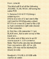
If you want the Clarifier locked, put the parts back together as in the schematic below.
To unlock Clarifier:
First lets look at what the clarifier mod should be:


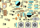
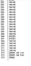
Remove/clip D69 - this removes the TX voltage from the circuit.
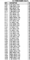
Remove R197 - this removes RX voltage from the circuit
1K precision trimmer (Bourns) Preparation:
You are only going to need the middle and an end leg (doesn't matter which); cut one end leg off and bend the other end leg 90 degrees (sticks out).
Adjust Brass screw for 100ohms between the 2 legs.
Wire and insulate a 8" piece of wire to the end leg sticking out from the trimmer.
Where the bare wire of R197 was just below J118, solder the middle leg of the precision trimmer (connects to red wire on J118).
Make sure R198 is intact and not jumped - this helps you slide down
Make sure D61 is intact and not jumped - this drops the voltage .7v
Connect the wire from the trimmer to a constant, stable 8v source (8v pin of IC6 or IC16). Measure both to find the one that changes the LEAST between RX & TX and use that one (less than .02v at least).
Alignment:
You need a good 8 digit Freq. counter to do this correctly.
First adjust L27 for mid tuning range (screw the slug up or down).
In AM mode, while looking at the freq. counter, turn the clarifier until it reads 10.695000 MHz +/-10Hz or as close as you can get (don't worry about the clarifier position; we will take care of that later). Adjust the slug if necessary to get it exactly on freq.
Don't move the clarifier any more!
In LSB mode, adjust L28 for 10.697500 MHz +/-10Hz on the freq. counter.
In USB mode, adjust L29 for 10.692500 MHz +/-10Hz on the freq. counter.
This gets all 3 modes "aligned".
Next, adjusting the Clarifier for 12:00:
Measure the voltage on the wiper (center) connection of the Clarifier (Brown wire on J118) and note the position of the clarifier. Write that down. That is the voltage that needs to be output when the clarifier is @ 12:00.
Now move the Clarifier to 12:00. Is the voltage higher or lower?
If the voltage is higher, then the voltage coming out of the clarifier needs to be reduced. With the Clarifier @12:00, adjust the precision trimmer to match the voltage that you wrote down.
If you can't adjust the voltage down enough with the trimmer, use a 5K trimmer.
Rare - If you can't adjust the voltage up enough, start the "Alignment" process with the clarifier turned a little more CCW from the original position used the first time to "Align". Then just adjust L27, L28, and L29 for freq.
*********************Easier Method to Unlock Clarifier**********************
Basically using the existing VR21 instead of a precision trimmer.
Another option that is easier to make the clarifier slide is lift the leg of R185 opposite VR21 and attach the 8v source to it.
Remove D69 - this removes the TX voltage from the circuit.
Remove R197 - this removes RX voltage from the circuit
Make sure R198 is intact and not jumped - this helps you slide down.
Place a jumper in the hole where the anode end of D69 was (connects to VR21) to the hole left by R197 that connects to the red wire in J118 (right below J118).
Make sure D61 is intact and not jumped - this drops the voltage .7v.
Adjust VR21 to change clarifier voltage. It now has constant voltage instead of TX only.
The 5K VR21 isn't a precision trimmer so it will be more challenging to get things on Freq.
Good Luck!
Last edited:


