• You can now help support WorldwideDX when you shop on Amazon at no additional cost to you! Simply follow this Shop on Amazon link first and a portion of any purchase is sent to WorldwideDX to help with site costs.
  • Click here to find out how to win free radios from Retevis!

OLD GALAXY SATURN EPT360011B

RF Krazy

New Member
Dec 1, 2023
12
5
3
59
Hello,

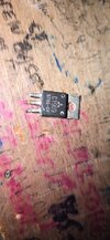
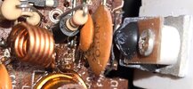
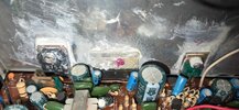
I have a GALAXY SATURN that was working fine until the finals went down.

I am getting a few watts out so I am asuming the driver is good.

Can anyone tell me what finals are installed? Also there are what look like caps of sorts that are piggy back on the finals.
Thats why I cannot tell what they are.

What are these for, as I have never seen these (Caps) as I am very old school and probably older then most here! There are two finals.
Did Galaxy install two Bipolars back then or would these be Mosfet?

What ever they are, can they still be purchased? Can someone please give me the scoop on where to go from here, or the 411 !!!

I can replace them and I can bios them, I just need to know what to buy and where?

Thank you all for your insight, your experience, and for your valuable information!

RF Krazy
 
  • Like
Reactions: secret squirrel

Pretty sure that version used the Mitsubishi 2SC2312. It was discontinued almost 20 years ago. A chinese outfit called Hua Gao makes them now. Counterfeits appeared seemingly everywhere after the European Union's lead-free mandate prompted the end of its production. MOSFETs did not appear in this kind of radio until bipolars disappeared in the lead-free fiasco between 2006 and 2007.

These guys have the genuine "HG" copy.

https://www.icamanufacturing.com/shop/p/hg-2sc2312

They also have the HG copy of the nearly-identical 2SC1969. My advice is to read the numbers from the old parts and use that as a replacement.

When those fail, they tend to short inside and shoot the power-supply voltage from the collector circuit out the input terminal, the base. This toasts the bias diode, a 1-ohm resistor with a ferrite bead on one end and the bias trimpot. Simply dropping in a new final transistor will sometimes result in the new part being POOFED more or less right away. Once the base circuit and bias parts are known to be good it's safe to solder the leads on new finals.

The "-12" circuit board dates to around 30 years ago. Got replaced by the "14B" board in the mid-90s. The final section of the later 14B board is pretty much the same. Biggest differences are in the PLL section.

But that's been my experience, new bias trimpots, bias diodes and one fixed resistor on each final. Those trimpots will get 'dirty' or oxidized like a scratchy volume control. Good idea to replace them even if they weren't toasted in the breakdown.

73
 
Last edited:
Hello Nomadradio,

You always amaze me with your knowledge and your willingness to share.
(Dating back to CBTricks).

I recently emailed you about a possible replacement
about the 2879s using the same circuit as the possible replacement.
Thank you for your reply back.

Can you please tell me what looks like capacitors piggy backing the finals
are on the Saturn? As you know caps are used for resonates and also
to help energize circuits, block circuits and so on, but I am not sure about these.

You are surely an amazing person, thank you.

73
RF Krazy
 
  • Like
Reactions: secret squirrel
Pretty sure that version used the Mitsubishi 2SC2312. It was discontinued almost 20 years ago. A chinese outfit called Hua Gao makes them now. Counterfeits appeared seemingly everywhere after the European Union's lead-free mandate prompted the end of its production. MOSFETs did not appear in this kind of radio until bipolars disappeared in the lead-free fiasco between 2006 and 2007.

These guys have the genuine "HG" copy.

https://www.icamanufacturing.com/shop/p/hg-2sc2312

They also have the HG copy of the nearly-identical 2SC1969. My advice is to read the numbers from the old parts and use that as a replacement.

When those fail, they tend to short inside and shoot the power-supply voltage from the collector circuit out the input terminal, the base. This toasts the bias diode, a 1-ohm resistor with a ferrite bead on one end and the bias trimpot. Simply dropping in a new final transistor will sometimes result in the new part being POOFED more or less right away. Once the base circuit and bias parts are known to be good it's safe to solder the leads on new finals.

The "-12" circuit board dates to around 30 years ago. Got replaced by the "14B" board in the mid-90s. The final section of the later 14B board is pretty much the same. Biggest differences are in the PLL section.

But that's been my experience, new bias trimpots, bias diodes and one fixed resistor on each final. Those trimpots will get 'dirty' or oxidized like a scratchy volume control. Good idea to replace them even if they weren't toasted in the breakdown.

73
Hello Nomadradio,

I am stunned. The bipolar ended up being a 1969.
Does this make any sense? I have only clipped the one out for now
with a pair of cutters. I am not sure when I will get back to it and
I didn't want to disturb the board in anyway. This way when I do the work
everything will be fresh in my old mind of mine!

So I am assuming I should order two of the...
"HG copy of the nearly-identical 2SC1969"

I will wait for sound advice. I hope you don't mind.

Thank you as always.
RF Krazy
 

Attachments

  • 1969 bipolar copy.jpg
    1969 bipolar copy.jpg
    2 MB · Views: 14
Yeah, use the same part type found in the radio. Just which Galaxy models used the 2312, and which ones the 1969 always seemed kinda random to me. Just take precautions you don't poof the new parts when they're installed. Might want to take a DC meter, put the ground onto the negative side of the big filter cap, and poke the positive probe to the "mirror" board. It's a jumper in the form of a tiny circuit-board biscuit held in place by three fork-shaped contacts, just to the front from the driver and finals. The exposed surface should read between 5 and 8 Volts more or less with the mike keyed on AM. Turning the power knob should change the reading. If it shows a steady reading over 12 Volts that won't change with the Power knob, you have additional faults to clear up.

73
 
  • Like
Reactions: secret squirrel
Yeah, use the same part type found in the radio. Just which Galaxy models used the 2312, and which ones the 1969 always seemed kinda random to me. Just take precautions you don't poof the new parts when they're installed. Might want to take a DC meter, put the ground onto the negative side of the big filter cap, and poke the positive probe to the "mirror" board. It's a jumper in the form of a tiny circuit-board biscuit held in place by three fork-shaped contacts, just to the front from the driver and finals. The exposed surface should read between 5 and 8 Volts more or less with the mike keyed on AM. Turning the power knob should change the reading. If it shows a steady reading over 12 Volts that won't change with the Power knob, you have additional faults to clear up.

73
Hello Nomadradio,

I am familiar with the mirror board as I have a Galaxy 949 that has one in it.
I was not familiar with the procedure that you had now taught me with DC meter though and the power adjustment. (Thank you)
My voltage readings were low compared to yours.

Maybe because of the finals being blown and now with one being removed? The voltages were 2.11 with the control turned to the far left,
and 6.37 with the control turned to the far right.

The final potentiometers that you mentioned aren't the cheaper plastic ones.
Is it possible that they may be okay? You mentioned about replacing those.
Would you have an idea where to purchase them and what the values are?

Thank you,
73
RF Krazy
 
  • Like
Reactions: secret squirrel
When they are running right the old Saturns rock and roll. We had a local lady who would talk every night on a Saturn and she really sounded well, like TV audio. That's back when everyone ran an IMAX and about 8 people around town still talked in evenings and smoked cigarettes, opened up the Jim Beam bottle. People moved, people passed. I was nice to flip channels and hear the locals.
 
  • Like
Reactions: Shadetree Mechanic
Yeah, use the same part type found in the radio. Just which Galaxy models used the 2312, and which ones the 1969 always seemed kinda random to me. Just take precautions you don't poof the new parts when they're installed. Might want to take a DC meter, put the ground onto the negative side of the big filter cap, and poke the positive probe to the "mirror" board. It's a jumper in the form of a tiny circuit-board biscuit held in place by three fork-shaped contacts, just to the front from the driver and finals. The exposed surface should read between 5 and 8 Volts more or less with the mike keyed on AM. Turning the power knob should change the reading. If it shows a steady reading over 12 Volts that won't change with the Power knob, you have additional faults to clear up.

73
Here is a Galaxy Saturn service manual. It shows the 2166 driver and 2312 finals. I'd lay odd that someone swapped in the 1969s in place of the 2312s.
 

Attachments

  • galaxy_saturn_service.pdf
    10.9 MB · Views: 12
  • Like
Reactions: Shadetree Mechanic
It was common to find Saturn radios from that era with the metal surface of the finals' metal tabs turned a flat black from the heat. The factory would run the bias-current setting way higher than it should have. The oxidation would get really thick. After a year or three one or both finals would fail from excessive operating temperature and get replaced.

Would be rare for a radio that old to have factory-original final transistors. No telling how many times they have been replaced.

Or how many damaged input-circuit parts are hiding in there.

73
 
Thank you for the service manual 999.

What is this device piggy backed on the final? Is it a Cap, a heat sensor or ?

And what is its purpose?

Nomadradio, looking through the inside its very obvious there has been
someone or many who has had their hands in there replacing parts.
Even the audio chip and such has been replace.
This radio needs a lot of cleaning up, thats for sure.
 

Attachments

  • Final Transistor.jpeg
    Final Transistor.jpeg
    95.1 KB · Views: 13
  • Audio Chip.jpeg
    Audio Chip.jpeg
    101.5 KB · Views: 12
What is this device piggy backed on the final? Is it a Cap, a heat sensor or ?

And what is its purpose?
Hi. That device, mounted onto the transistor, is likely a biasing diode and it tracks the temperature of the transistor, adjusting slightly the biasing conditions as it heats up.
 
Hi. That device, mounted onto the transistor, is likely a biasing diode and it tracks the temperature of the transistor, adjusting slightly the biasing conditions as it heats up.
Thank you Cable Guy.

I wonder if this is what Nomadradio met by taking out the diodes? I looked around the final circuit on the board and I didn't see any diodes so maybe these are the diodes that Nomadradio was talking about?
 
Thank you Cable Guy.

I wonder if this is what Nomadradio met by taking out the diodes? I looked around the final circuit on the board and I didn't see any diodes so maybe these are the diodes that Nomadradio was talking about?
I'd say so, I don't have the 11b schemo handy but the 14b schemo I have here, there are no additional diodes in the final pa section, and only one other, a 1n4148 diode, in the driver section called D90. I'd use the diode check on your DMM on the two MV1Y diodes (the ones attached to the transistors) for sure. Good luck!

1726264643045250437117939963812.jpg
 
Yeah, don't take them out (unless testing the diodes, should remove at least 1 leg for testing purposes) but never leave them out. They may have been "taken out" (destroyed) so check them before replacing the finals, check the biasing resistor and the VR pot that sets bias. Check it all, else you may be sorry.
 
  • Like
Reactions: 999

dxChat
Help Users
  • No one is chatting at the moment.