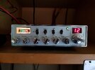
This radio is as old as the Apple Macintosh. Date codes on the chips that have them are 1984.
No, it doesn't say "Galaxy" anywhere on it. But only inside it.
Sorta.

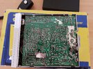
This circuit board number doesn't start with the letters "EPT", but it's the same format and the lowest "3600" followed by "10".

The older "Excalibur" radios were made by Cybernet in Japan. Not my favorite radio. Had stability issues.
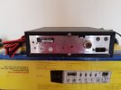
This one says "Taiwan".

At the height of CB-radio market hype there was a factory in Taiwan supplying CB radios to a company called Fanon/Courier. Like nearly all name brands of CB radio in the early 80s, they evaporated never to be heard from again. An enterprising Taiwan businessman named Jim Peng bought the factory, forming the start of "Ranger Communications International". At first they did the way Uniden had done back in the day. Supplying radios to retail brands on contract. Don't know who owned the "Excalibur" name but if you see one that says "Colt Excalibur" on the front don't get too excited. It's a 40-channel only legal CB, and not a terribly good one, if memory serves.
Eventually they started putting their name on the outside of the radio.
But this one is old. Came in with a complaint of "poor receive". Found that the power supply was jamming 23 Volts into the radio. This usually blows the speaker-amp chip to the devil. Just made this one sound terrible. Apparently terrible enough to shut it off BEFORE the first overloaded part could go "SNAP!". Decided not to repair the old analog regulator.

The small 50-Watt chinese switchmode "bricks" are the most cost-effective cure for this problem. This one was putting some RF hash into the receiver. Only heard on the dummy load, but that's bad enough. A .01uf disc cap each from the V- and V+ DC output terminals was all it took to make the noise go away.

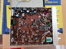
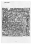
In the wide view of the circuit boards above, the upper-right corner reveals a pcb installed where most "black" radios have only an empty rectangular hole with two screw tabs.

The "EPT0SSB" number on this board pretty well settles where it came from. The blue relay is the antenna A/B switch. The radio was made with two antenna sockets, but when the relay got flaky it was bypassed to a single antenna socket.
This radio has a Galaxy FC347 external frequency display. The long shielded lead has a lot of capacitance to ground, and would load down the output of the PLL and reduce receiver/transmit performance. Adding a cap with small-enough capacitance to stop the loading would not feed sufficient signal to the counter, and the reading would "dance". Here is a buffer amplifier we hacked to fix this issue. Not happy with how clear the pics show the setup. No schematic. Too simple for that. The left lead of the J310 FET is the drain. It gets two things. A .01uf cap to ground, and a wire to the regulated 9 Volts that powers the PLL section. Center lead is the source. Gets a 330 ohm 1/4W resistor to ground, and a 100pf disc cap. The cap's other end feeds out to the center wire of the counter coax. The right-hand lead is the gate. It gets plastered directly to the output pad of L18, the PLL output. Newer circuit boards have a buffer-amp circuit that feeds the input of the radio's built-in frequency display. This is why.

This cured the loading/performance problem.
Didn't include a pic showing how many of the small gray trimmer capacitors had to be tacked on under a tuneable coil with a bad internal cap. This radio has five. Not a record. Does suggest it spent some time in somebody's damp basement since 1985. I'm convinced that humidity exposure is what makes the internal caps in these slug-tuned "cans" go bad.
This radio brings to mind the old saying "More issues than National Geographic". With any luck it will hold together for a while longer down the road.
73
No, it doesn't say "Galaxy" anywhere on it. But only inside it.
Sorta.

This circuit board number doesn't start with the letters "EPT", but it's the same format and the lowest "3600" followed by "10".

The older "Excalibur" radios were made by Cybernet in Japan. Not my favorite radio. Had stability issues.
This one says "Taiwan".

At the height of CB-radio market hype there was a factory in Taiwan supplying CB radios to a company called Fanon/Courier. Like nearly all name brands of CB radio in the early 80s, they evaporated never to be heard from again. An enterprising Taiwan businessman named Jim Peng bought the factory, forming the start of "Ranger Communications International". At first they did the way Uniden had done back in the day. Supplying radios to retail brands on contract. Don't know who owned the "Excalibur" name but if you see one that says "Colt Excalibur" on the front don't get too excited. It's a 40-channel only legal CB, and not a terribly good one, if memory serves.
Eventually they started putting their name on the outside of the radio.
But this one is old. Came in with a complaint of "poor receive". Found that the power supply was jamming 23 Volts into the radio. This usually blows the speaker-amp chip to the devil. Just made this one sound terrible. Apparently terrible enough to shut it off BEFORE the first overloaded part could go "SNAP!". Decided not to repair the old analog regulator.

The small 50-Watt chinese switchmode "bricks" are the most cost-effective cure for this problem. This one was putting some RF hash into the receiver. Only heard on the dummy load, but that's bad enough. A .01uf disc cap each from the V- and V+ DC output terminals was all it took to make the noise go away.

In the wide view of the circuit boards above, the upper-right corner reveals a pcb installed where most "black" radios have only an empty rectangular hole with two screw tabs.

The "EPT0SSB" number on this board pretty well settles where it came from. The blue relay is the antenna A/B switch. The radio was made with two antenna sockets, but when the relay got flaky it was bypassed to a single antenna socket.
This radio has a Galaxy FC347 external frequency display. The long shielded lead has a lot of capacitance to ground, and would load down the output of the PLL and reduce receiver/transmit performance. Adding a cap with small-enough capacitance to stop the loading would not feed sufficient signal to the counter, and the reading would "dance". Here is a buffer amplifier we hacked to fix this issue. Not happy with how clear the pics show the setup. No schematic. Too simple for that. The left lead of the J310 FET is the drain. It gets two things. A .01uf cap to ground, and a wire to the regulated 9 Volts that powers the PLL section. Center lead is the source. Gets a 330 ohm 1/4W resistor to ground, and a 100pf disc cap. The cap's other end feeds out to the center wire of the counter coax. The right-hand lead is the gate. It gets plastered directly to the output pad of L18, the PLL output. Newer circuit boards have a buffer-amp circuit that feeds the input of the radio's built-in frequency display. This is why.

This cured the loading/performance problem.
Didn't include a pic showing how many of the small gray trimmer capacitors had to be tacked on under a tuneable coil with a bad internal cap. This radio has five. Not a record. Does suggest it spent some time in somebody's damp basement since 1985. I'm convinced that humidity exposure is what makes the internal caps in these slug-tuned "cans" go bad.
This radio brings to mind the old saying "More issues than National Geographic". With any luck it will hold together for a while longer down the road.
73


