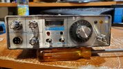
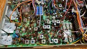
I have a really clean Pace Sidetalk 1000m I hate to throw this radio out in the trash or use it for parts if it's a simple fix the issue with the radio is it does not fully power up. There is no light on AM USB or LSB lamps also the channel selector lamp and meter light are not working. The RX and TX lamps work and when the mic is keyed the relay is clicking. There is also no receive or power output. Any ideas? Thanks
You are using an out of date browser. It may not display this or other websites correctly.
You should upgrade or use an alternative browser.
You should upgrade or use an alternative browser.
-
You can now help support WorldwideDX when you shop on Amazon at no additional cost to you! Simply follow this Shop on Amazon link first and a portion of any purchase is sent to WorldwideDX to help with site costs.
Pace Sidetalk 1000M Problem
- Thread starter HavaV10
- Start date
What I remember about this model is that the double-sided printed-circuit design caused repeated intermittent failures.
A printed circuit board with foil traces on both sides wasn't widely used in a CB radio design 45-plus years ago. Even today, single-sided circuit boards dominate among models introduced before Y2K, and plenty of them made since then.
The problem lies with connections that bridge from one side to the other side of the circuit board. They didn't use plate-through copper sleeves inside each hole, but small copper pins. I have heard them called "griplets", but I have no idea where that name comes from. The solder will develop fatigue cracks around these pins, and connections will come and go.
This is a 23-channel radio, and a dirty channel selector can disable the radio entirely. See if cleaning the black silver oxide off of the contacts has any benefit.
73
thanks I did use detoxit on the channel selector but that didn't do anything. I will look into some more soon. Would really like to get this thing going. Thanks.What I remember about this model is that the double-sided printed-circuit design caused repeated intermittent failures.
A printed circuit board with foil traces on both sides wasn't widely used in a CB radio design 45-plus years ago. Even today, single-sided circuit boards dominate among models introduced before Y2K, and plenty of them made since then.
The problem lies with connections that bridge from one side to the other side of the circuit board. They didn't use plate-through copper sleeves inside each hole, but small copper pins. I have heard them called "griplets", but I have no idea where that name comes from. The solder will develop fatigue cracks around these pins, and connections will come and go.
This is a 23-channel radio, and a dirty channel selector can disable the radio entirely. See if cleaning the black silver oxide off of the contacts has any benefit.
73
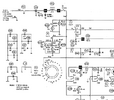
I'm not the brightest Crayon in the box... so I hope the image I attached comes through..........
This is likely to be EXACTLY what Nomad says and here is why I think so....
If you take a look at the schematic section..... the mode switch lights AND the meter lights ALL come right straight off of the switch.... the main power rail. Those are not working..... YET.... the RX/TX lights ARE working... and the relay is "picking".... and we KNOW that those won't work UNLESS the main power rail is up.
THAT means..... the main power rail is "up in some places" and "not up in others".... which means we are probably looking at a PC board "pass through" issue.
SBE had the same thing on my ConsoleV and the SBE service manual had one particular PC board drawing that had each and every pass through marked. I just looked in the SAMS for the 1000M and there is no such drawing there (same in the SBE the SAMS did not have that nice pic!).
If you really want to save it, I am thinking that you may need to focus on the DC power supply page in the SAMS.... take EACH supply by the SAMS "Circuit Trace" number..... and scour the radio, section by section, with a DMM and see where each "supply circuit IS and ISN'T".. That may help lead you to isolate a certain section of the PC board trace that SHOULD be powered but isn't. When that section is NOT powered.... IT may feed OTHER sections and they will also be down.
If you can organize all of that info.... (which are working and which are not) and examine it against the SAMS power supply.... it MAY help you find out the "topmost level" of the PC board traces that are not working.... which may lead you to find the pass through that is bad. The "higher up in the level" that the failure is occurring..... the more "lower level" supplies may also be dead..... but that depends on how the PC board is laid out and how the pass throughs are located.
I think that, in this case, your best friend is going to be the SAMS... and using those CircuitTrace numbers to your advantage..
Unfortunately, the PC board images in the SAMS leave a little to be desired. They are grainy and don't "expand" well when you expand a snippet.... but they may be the best you've got. A good magnifying hood or glasses may also be your friend here.
I have tried to attach a ZIP of a folder of all of the CBTRICKS content... as I tried to read the service manual there and it said that the file could not be found.
I had it already, so I zipped it all up and attached it here in the hopes that it might have one or several pieces of a solution for you!
Best of luck!
Attachments
thank you Guitar 199I'm not the brightest Crayon in the box... so I hope the image I attached comes through..........
This is likely to be EXACTLY what Nomad says and here is why I think so....
If you take a look at the schematic section..... the mode switch lights AND the meter lights ALL come right straight off of the switch.... the main power rail. Those are not working..... YET.... the RX/TX lights ARE working... and the relay is "picking".... and we KNOW that those won't work UNLESS the main power rail is up.
THAT means..... the main power rail is "up in some places" and "not up in others".... which means we are probably looking at a PC board "pass through" issue.
SBE had the same thing on my ConsoleV and the SBE service manual had one particular PC board drawing that had each and every pass through marked. I just looked in the SAMS for the 1000M and there is no such drawing there (same in the SBE the SAMS did not have that nice pic!).
If you really want to save it, I am thinking that you may need to focus on the DC power supply page in the SAMS.... take EACH supply by the SAMS "Circuit Trace" number..... and scour the radio, section by section, with a DMM and see where each "supply circuit IS and ISN'T".. That may help lead you to isolate a certain section of the PC board trace that SHOULD be powered but isn't. When that section is NOT powered.... IT may feed OTHER sections and they will also be down.
If you can organize all of that info.... (which are working and which are not) and examine it against the SAMS power supply.... it MAY help you find out the "topmost level" of the PC board traces that are not working.... which may lead you to find the pass through that is bad. The "higher up in the level" that the failure is occurring..... the more "lower level" supplies may also be dead..... but that depends on how the PC board is laid out and how the pass throughs are located.
I think that, in this case, your best friend is going to be the SAMS... and using those CircuitTrace numbers to your advantage..
Unfortunately, the PC board images in the SAMS leave a little to be desired. They are grainy and don't "expand" well when you expand a snippet.... but they may be the best you've got. A good magnifying hood or glasses may also be your friend here.
I have tried to attach a ZIP of a folder of all of the CBTRICKS content... as I tried to read the service manual there and it said that the file could not be found.
I had it already, so I zipped it all up and attached it here in the hopes that it might have one or several pieces of a solution for you!
Best of luck!
Radio now fully powers up. Found a bad 100uf 16V cap. Still don't have receive or transmit. I have about 10 more caps to replace.
THAT would be a much easier solution than hunting for a bad pass through......
For future restorations, I have an electrolytic capacitor kit for the 23 channel as well the 40. See link below;
https://klondikemikescapkits.com/pr...trolytic-capacitor-kit?variant=40640907182165

https://klondikemikescapkits.com/pr...trolytic-capacitor-kit?variant=40640907182165

You have to be careful with those double sided boards when replacing parts.
I snagged a hr 2600 one time for cheap at the flea market.
The guy had a bunch of random electronics and in the mix i see this old hr2600 box.
I asked what's that?
He says it is a CB, he did not know anything about it and he would take $25.
I opened the box to look at the radio, its clean and then I see there is a black ChipSwitch box in the bag with the mic/mounting bracket and power cord.
I thought ok, this might be interesting.
How bout 20?
Deal.
Got to the car, opened the chipswitch box to find the stock 2600 cpu.
Drive home,
pull the cover off and there is a socket installed but no chipswitch.
Oh well.
Then I started looking at the cpu in the box and I could actually see 3 pins that still had the tiny through hole sleeve soldered to the pin.
Someone had pulled them out of the board when he removed it.
I removed the socket , put the CPU back in and made sure to flow the top/bottom of those 3 pins well.
Radio fired right up and everything functioned.
If not for that old chip I would not have noticed those pins.
Also glad I did not go down that rabbit hole...
73
Jeff
I snagged a hr 2600 one time for cheap at the flea market.
The guy had a bunch of random electronics and in the mix i see this old hr2600 box.
I asked what's that?
He says it is a CB, he did not know anything about it and he would take $25.
I opened the box to look at the radio, its clean and then I see there is a black ChipSwitch box in the bag with the mic/mounting bracket and power cord.
I thought ok, this might be interesting.
How bout 20?
Deal.
Got to the car, opened the chipswitch box to find the stock 2600 cpu.
Drive home,
pull the cover off and there is a socket installed but no chipswitch.
Oh well.
Then I started looking at the cpu in the box and I could actually see 3 pins that still had the tiny through hole sleeve soldered to the pin.
Someone had pulled them out of the board when he removed it.
I removed the socket , put the CPU back in and made sure to flow the top/bottom of those 3 pins well.
Radio fired right up and everything functioned.
If not for that old chip I would not have noticed those pins.
Also glad I did not go down that rabbit hole...
THAT would be a much easier solution than hunting for a bad pass through......
73
Jeff
That is good to know KM! Because I also have this exact radio in my stash for a future project!For future restorations, I have an electrolytic capacitor kit for the 23 channel as well the 40. See link below;
https://klondikemikescapkits.com/pr...trolytic-capacitor-kit?variant=40640907182165
Thanks, Bob
He has good quality caps (I've bought at least a half dozen kits from him)That is good to know KM! Because I also have this exact radio in my stash for a future project!
Thanks, Bob
Would you know if the 40ch. version of this have a double-side pcb as well?What I remember about this model is that the double-sided printed-circuit design caused repeated intermittent failures.
A printed circuit board with foil traces on both sides wasn't widely used in a CB radio design 45-plus years ago. Even today, single-sided circuit boards dominate among models introduced before Y2K, and plenty of them made since then.
The problem lies with connections that bridge from one side to the other side of the circuit board. They didn't use plate-through copper sleeves inside each hole, but small copper pins. I have heard them called "griplets", but I have no idea where that name comes from. The solder will develop fatigue cracks around these pins, and connections will come and go.
This is a 23-channel radio, and a dirty channel selector can disable the radio entirely. See if cleaning the black silver oxide off of the contacts has any benefit.
73
I have four of this model. Only one works well. The other is AM only. SSB has no output. Hope you get yours going!
To the best of my recollection it does.Would you know if the 40ch. version of this have a double-side pcb as well?
73


