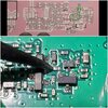
If you can read that chip and it says 102 - then you've got the one they claim IS THE ONE TO REMOVE...
To me, the MOD circuit is similar to the ones used by PC-122 and others where a Difference signal is generated then applied to a differential amplifier - and hence your clamping problem
Galaxy does similar but use it for their Envelope Control - when you change carrier - the drive level output from the Sense circuit is also reduced, so to compensate, they simply "rebias" the comparator input with the new power level and you still have the same level of scale.
To solve that problem we have to remove that Envelope Control transistor...
On these - it may not be as easy - for they did set these up with circuits that "hang up" if they have no place to go - so if you remove a part - that may make matters worse and the radio won't even work at all.
View attachment 35196
But I did find the AM Regulator in the schematic - Note the AMMOD line - it's the output side of this circuit and so the line is labeled as such in the schematic over by where the Mod Amp is.
As part of that "fool-resistant" design - the Mod clamp circuit simply uses the diode a lot like the PC-122 and Cobra designs using the Diode to clamp - by flowing into the Transistor that operates the limiter AMC control higher up (relative term - towards the center of the page) in the Schematic. There isn't a true variable applied here - just the bias setting for DC-level and then when you modulate the AVG DC bias level drops because the Audio is mixing in with it, making it unsteady and so the power appears to drop - so that is where it gets the "power" to drop so quickly it's clamping - the AVG power detect that the diode sees in comparison to normal DC bias.
IT may be easier to force a recovery of the limiter action by placing a low-value resistor ACROSS the diode instead...that way the clamping ACTION is not one-way all the time - you can recover to AVG faster if you provide a path for the power to be recouped before the next clamping action occurs.


