If the output impedance of a transistor is dependant on the output power, why are there so many references to power mods (just turn this pot or clip that whatever) but there is never any mention about retuning the L match between the final and filter network with it? Is that why so many people have SWR issues connecting to a linear meant to be driven by 50Ω?
You are using an out of date browser. It may not display this or other websites correctly.
You should upgrade or use an alternative browser.
You should upgrade or use an alternative browser.
-
You can now help support WorldwideDX when you shop on Amazon at no additional cost to you! Simply follow this Shop on Amazon link first and a portion of any purchase is sent to WorldwideDX to help with site costs.
-
A Winner has been selected for the 2025 Radioddity Cyber Monday giveaway! Click Here to see who won!
Stupid question time (transistor impedance @ wattage - effect on SWR).....
- Thread starter brandon7861
- Start date
I hear stories about how their match is perfect without the amp, and I always assumed it was the input tune in the amp, but is it possible it is because the radio is not 50Ω and the antenna was tuned to match that non-50Ω load before the amp was added (screwing up the match on both sides)?
I'll be watching this thread.
I have a linear that the SWR goes up to 1.4-1 when it's inline.
And I'll ask: would an antenna matcher between the rad/lin help?
I have a linear that the SWR goes up to 1.4-1 when it's inline.
And I'll ask: would an antenna matcher between the rad/lin help?
The output impedance does not effect swr. It only serves the coupling efficiency. It effects the power output like the tune knob on a tube amplifier. If the amplifier being inline changes the swr then it's the amplifier doing it.
Please help me understand this then, because when I take the datashet impedance off the datasheet to the Cobra2000 (2sc1969 with an output impedance of 5.5-j5.6 @12v and 13w) and plot the network from that radio on the smith chart, I can see a reasonable match at that power level. But when I use the formula Z=Vcc^2/(2*Watts) to approximate the output impedance (from Lou's book, which correlates well with the datasheet at the recommended wattage) and figure the impedance at other wattages, the match falls apart.The output impedance does not effect swr. It only serves the coupling efficiency. It effects the power output like the tune knob on a tube amplifier. If the amplifier being inline changes the swr then it's the amplifier doing it.
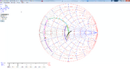
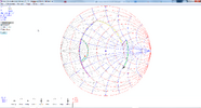
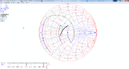
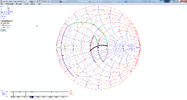
Without changing any component values, I get the following changing the impedance of the transistor.
This is with the datasheet impedance

This is with the calculated impedance at 4 watts

And this is with the calculated impedance at 20 watts

I can see how one might assme the half wave filter is 50Ω on the output when one designs it for that as Lou's book suggests, but that is only true if the input of that filter also sees its designed impedance (and thats what changes with power level). Are you saying that, within reason, the SWR won't change enough to be a problem, or are you saying that the SWR doesn't change at all? I'm confused now because the math says it changes...
To me, that looks like enough of an SWR shift that by someone simply changing the output power of their radio, they lost that purely resistive 50Ω impedance and should actually expect a 1.5:1 into an amplifier. Its just my theory anyhow, I'm just starting to learn this stuff so maybe I'm wrong.. Turning the power dial on my 979 changes the SWR reading too, so maybe.
You - in your work, just helped answer your own question.
In the INPUT Admittance side of the L-filter - there are two things going on.
A series pass into a parallel pass circuit.
Both are a transformation, but due to the multiple elements they include, you can think of one filter to another - then those two series into another - which is a filter yes, but is also the 50 ohm transformation that provides the filter due to the process of taking that low-impedance input from the finals output side, into that triple L filter but as a step to step to step impedance transformation window each time.
So, the conversion process is not as efficient as what it could be, but remember too, it is a filter - to be a Bandpass filter for the 27MHz signal.
When someone tunes that slug - the output of the transistor is "tuned" as a series pass to meet the input impedance of the first element of a triple L filter.
It is best to break down the elements - these circuits - into separate transformations - then the issue of how they merge the impedance from one side - transformed - into the 50Ω you'd want for the unbalanced output is better understood - at least you would know why they used the values of capacitance they did as a means of a working window of admittance that the coil would not have enough "Q-factor" to make a difference on.
The keyword is unbalanced - so the load is a reactive (or in the realm of resistive - dummy loading) 50 ohm impedance.
Last edited:
I doubt it. You will probably add more loss having the tuner in line than you have with that SWR. 1.4 is ok.would an antenna matcher between the rad/lin help?

