• You can now help support WorldwideDX when you shop on Amazon at no additional cost to you! Simply follow this Shop on Amazon link first and a portion of any purchase is sent to WorldwideDX to help with site costs.
  • Retevis is giving away Radios for the New Year and Every Member is Eligible. Click Here to see the details!

To top load or not cb mobile

nfsus

Yeah its turned off, touch it
May 9, 2011
522
278
73
48
Arkansas
I have run both 102 and loaded whips. Base load center load and top load. I’ve read all the trash on each one about compromise and on and on.

1/4 wave being my choice of whip I have to wonder, height being such a factor in any plot you see i am always looking for better or different.

What’s going to work better on the same mount, ball and spring, on the same location? 5/8 top load like a fire stick or a full 1/4 wave 102 whip? The tip of the 102 will be higher of course.
 

The tip of the 102 will be higher of course.
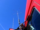
The tip is the spot of lowest current, highest voltage and therefore less radiation. The height of the feedpoint is much more important, especially in the always compromised mobile set-up.

7 3
 
If a quarter wave verticals on a vehicle is the top half of a half wave dipole, then the stretch for current maximum lies in extending the length of the antennas top half. Correct? To do this you’d need to lengthen the antenna by a cap hat, a longer vertical, or a top load coil, correct?

or am I mixing dipole and groundplane up in my head in this case
 
For a caphat you need a rigid antenna mast to hold the weight. A cap hat will thereotically make the antenna longer and make the RF currents radiate towards the top and outward for a true top loading antenna. But it also makes for a less durable antenna because if anything hits it the rigid mast and cap won't likely survive.

However, This will make it comparable to a full quarterwave whip on 27 mhz.

You can make your own with available parts but it's pricey to that and is it worth it?

IMG_0602.JPG
 
  • Like
Reactions: AudioShockwav
For a caphat you need a rigid antenna mast to hold the weight. A cap hat will thereotically make the antenna longer and make the RF currents radiate towards the top and outward for a true top loading antenna. But it also makes for a less durable antenna because if anything hits it the rigid mast and cap won't likely survive.

However, This will make it comparable to a full quarterwave whip on 27 mhz.

You can make your own with available parts but it's pricey to that and is it worth it?

View attachment 71566
How’s the cap hat on your screwdriver work half way up the stinger?
 
  • Like
Reactions: AudioShockwav
I put that short piece there for a static ball, also an ornamental piece. It does add to the length some but the horizontal radials are still high enough up the mast to be a cap hat.

Here's a pic without it.

get_attachment_aspx_3-1.jpg
 
  • Like
Reactions: AudioShockwav
So how to pull the current? Cap hat?

Cap hats actually do have this effect, to some very small degree. Unfortunately you will never notice it as just having a cap hat will add more loss than whatever you would gain from said current manipulation. The only place with any antenna where I've seen capacitance appear to have a significant effect on the current distribution is the basket area of the Astroplane antenna, where modeling shows a 1/4 wavelength current distribution over a physical 1/2 wavelength of mast (or perhaps it was caused by something else, but no one had any ideas as to what the could be). You would have to look up those old threads for that discussion.

Loading coils actually have a similar effect as well. The current at the top of the load is very close (but not exactly) the same as the current at the bottom of the load. The problem is, the more length the load takes out of the antenna, the greater the difference in current. There was yet another old thread on this forum where we discussed (and tried to duplicate with modeling) a study that actually tried to use the effect on current to benefit the antenna pattern, but we could not get any noticeable benefits from said tests. Again, whatever we did added more loss then any detectable gain.


The DB
 
  • Like
Reactions: Crawdad
I won't argue against that, modeling shows the same. The real question that needs to be asked, however, is how much more efficient is the cap hat over a loading coil... What does you book say?


The DB
 
Cap hats actually do have this effect, to some very small degree. Unfortunately you will never notice it as just having a cap hat will add more loss than whatever you would gain from said current manipulation. The only place with any antenna where I've seen capacitance appear to have a significant effect on the current distribution is the basket area of the Astroplane antenna, where modeling shows a 1/4 wavelength current distribution over a physical 1/2 wavelength of mast (or perhaps it was caused by something else, but no one had any ideas as to what the could be). You would have to look up those old threads for that discussion.

Loading coils actually have a similar effect as well. The current at the top of the load is very close (but not exactly) the same as the current at the bottom of the load. The problem is, the more length the load takes out of the antenna, the greater the difference in current. There was yet another old thread on this forum where we discussed (and tried to duplicate with modeling) a study that actually tried to use the effect on current to benefit the antenna pattern, but we could not get any noticeable benefits from said tests. Again, whatever we did added more loss then any detectable gain.


The DB
Like a dog chasing his tail. Fun but kind of pointless.
 
There was yet another old thread on this forum where we discussed (and tried to duplicate with modeling) a study that actually tried to use the effect on current to benefit the antenna pattern, but we could not get any noticeable benefits from said tests. Again, whatever we did added more loss then any detectable gain.
I can give real world tests to what a cap hat does for the antenna.

In the mobile environment antennas are often shortened down for height reasons especially in amateur bands below 10 meters. This is what causes impedance mismatches at the antenna feedpoint and loading inductive coils are added to compensate. The lower the frequency means more coil needs to be used which means greater losses from using the coil. This is the trade off to run a shortened antenna on a lower band.

With a screwdriver antenna, a retractable loading coil is used to easily match the antenna for different bands. This makes the screwdriver the ideal mobile HF antenna because the ease of remote tuning for the HF bands.

With my screwdriver antenna and a 5 ft whip on 40 meters, It used just over 2/3rds of the coil to get a good match. While this works, it also means a lot of losses from that much coil. But, when I used a cap hat, I used a little less than half the coil to get the same match meaning far less coil losses. On the other end, there has been noted a full S unit of gain with the cap hat as opposed to the 5 ft whip in test that I have done.

A cap does make the antenna electrically longer which is always good but the gain comes from less loading coil losses which is even better. There is no gain over a dipole because it's still a vertical mobile antenna but there is gain with a mobile antenna with a caphat over a non caphat loaded coil antenna. Only a full quarter wave whip is still better for mobile antennas but a caphat would be just about as good without the height issues.

I have seen commercial broadcast radio use a caphat on their antennas before. This could be because of antenna height restrictions for an area or cost saving by having a lower height antenna.

Here's a pic of a radio station in Santa Fe Nm using a caphat.

20250114_085645.jpg
 
  • Like
Reactions: Crawdad

dxChat
Help Users
  • No one is chatting at the moment.