• You can now help support WorldwideDX when you shop on Amazon at no additional cost to you! Simply follow this Shop on Amazon link first and a portion of any purchase is sent to WorldwideDX to help with site costs.
  • Click here to find out how to win free radios from Retevis!

Tram D62/Cobra 132 no transmit on 36-40

Lkaskel

Well-Known Member
Aug 4, 2017
420
349
73
60
Hi Everyone,
So, on the bench is a Tram D62 which is the same radio as the Cobra 132 and is shown in Sams 179. This radio performs well overall but is sparatic in transmitting on 36, 37, 38, 39 and will will almost never transmit on 40. This is true on AM, LSB and USB. When you key the mic in AM (mic gain at 0) you will see deflection on the bench meter but the transmit light on the radio does not come on. I have carefully drilled a small hole in the side of the 3 channel selector housings and sprayed Deoxit F5 (green can) and spun the channel selector a ton with no change in performance.

Any Thoughts?
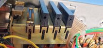

Channel Selector.jpg
 

It sounds like the VCO tuning range might be a bit off. I think the VCO tuning slug is L304, but just in case I am wrong, don't change it. Since it is struggling with higher frequencies, I would guess the slug needs to be backed out a bit.

One way to change a tuning inductor value without actually changing it is to bring another material close to the slug. Ferrite from junk core will increase the inductance, brass will decrease it. I have both on a little tuning stick I use to poke at things I don't want changed yet. Coat a little piece of brass brazing rod in fingernail paint (so its not conductive in case you drop it), and gently set it on that slug and see it if changes anything.

I'd wait for more opinions though :) someone here may be very familiar with that radio, I am not.
 
Only effective way I know to tweak the VCO's tuning-voltage adjustment is with a 'scope.

The schemo is here: https://cbtricks.org/radios/cobra/132xlr/graphics/cobra_132xlr_sch.pdf

This radio has a somewhat-wacky PLL setup.

In most SSB CB radios you have a carrier crystal that's above the SSB crystal filter's frequency "window", and one crystal that's below it. Or a circuit that tweaks one crystal a few kHz when selecting upper or lower sideband. Or AM.

This radio has only one carrier crystal, producing only one sideband at the IF (carrier) frequency.

Mixing it with a frequency below 27 MHz gets you the same sideband as the IF circuit is using. But changing the PLL to a frequency that many MHz ABOVE the channel frequency will invert USB to LSB.

And that's how this radio's PLL does this. Not by "shifting" a few kHz for each mode, but by using high-side injection to get the opposite sideband you get with low-side injection.

A surprising number of 23-channel crystal-controlled CB radios used this trick. This is the only 40-channel SSB CB I remember seeing with this trick designed into it.

I can't believe they don't show a test point for the VCO tuning voltage. A radio that drops out a few channels short of the top, or bottom of the band is probably running out of tuning-voltage range. Best place I can see to monitor the tuning voltage is where R302, R306, R314 and R346 all come together.

L302 gets set so the PLL stays locked from channel 1 to 40 in USB or AM mode. A meter just doesn't reveal what's going on terribly well.

L301 is set to provide a proper end-to-end tuning voltage that doesn't run into the floor or the ceiling, so to speak, when flipping from channel 1 to channel 40.

The radio is old enough that age alone may have caused the proper slug position in those two coils to move from where the factory set them.

The tuning voltage in a PLL is a dynamic thing. A meter alone doesn't reveal as much as a 'scope trace.

73
This is great info Nomad!!! Thank you very much. I'll use the scope to see if changing this makes a difference. Now, to get a night at the bench...that's the trick.
Thanks again!!
 
The PLL has a finite range of tuning voltage it can deliver to the VCO. The oscillator's trimmer coil will determine what range of frequencies that range of tuning voltage gets you.

If the PLL reaches it maximum tuning voltage before you get all the way up to channel 40, it can act this way. Likewise, if the VCO oscillator coil's slug is set too far the other way, you could lose channels 1 to 5.

Watching the tuning voltage on a 'scope will reveal if this is what's going on.

73
This may be a dumb question, forgive me, but does one really need a scope? Cant you just monitor the tuning voltage with a DMM and see it it stops going up with every click of the channel dial? And if it does stop going up incrementally with every click, couldn't you then just go to channel 40 and then adjust the oscillator slug until that voltage moves off its limit just a bit, perhaps a half a volt or so?
 
If everything is working smoothly and the tuning voltage is just clean DC voltage with no quirky spikes a meter is fine. And if a meter is what you have, it's best to hope there are no quirky gremlins hiding in the radio's PLL. If the tuning voltage is doing things it shouldn't do, a 'scope can tell you what a meter can't. And if it all works like it should, the meter tells you enough.

73
Hey Everyone,
I am back on the Tram D62. Nomad was correct and the alignment was the issue with the lack of 36-40. I am now working on the alignment and while the Cobra 132XLR docs are great there is 1 thing that has me baffled. There is an adjustment VR 206 and an IC TA7046 that is in the Tram (not in the Cobra) 7064that I cannot figure out what they are doing. Has anyone aligned a D62 and been able to figure this out? They are physically near the RF gain adjustment.

Thanks!!
 

Attachments

  • Tram D62 extra parts.pdf
    898.7 KB · Views: 5

dxChat
Help Users
  • No one is chatting at the moment.