• You can now help support WorldwideDX when you shop on Amazon at no additional cost to you! Simply follow this Shop on Amazon link first and a portion of any purchase is sent to WorldwideDX to help with site costs.
  • Click here to find out how to win free radios from Retevis!

Uniden Grant 4 Button PC409ac TX on every other channel

Jun 28, 2018
10
11
13
I have a Uniden Grant PC409ac that only transmits on every other channel. Ch1 TX, Ch2 no TX, Ch 3 AND 4 TX, Ch 5 no TX and so on. Changed 10v caps and cleaned the dreaded Uniden Brown Death Glue away and pulled parts to check for missing legs, all good.
Having a heck of time finding service manual and pointers.
 

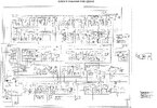
This is the clearest schematic I have of the PC-409. Should be about the same as the base (ac) version. I wish it was better, but given a substandard scan, there’s only so much enhancement that can be accomplish. At least most parts are readable. If anyone else has a better copy, please post.
 

Attachments

  • President Grant PC-409.jpg
    President Grant PC-409.jpg
    3.2 MB · Views: 15
  • Like
Reactions: 390 Wagonmaster
390,

You can use the service manual for the "Cobra 148GTL" which is very close to the "Grant PC409".

You can find some info here:
https://www.worldwidedx.com/ims/cobra-148-gtl.4/

There is a better service manual in the Sams Manuals (off hand I don't know which one), but "danmcclain" can more than likely post it (if he hasn't already) at:
https://www.worldwidedx.com/threads/sams-photofacts-collection.262787/

You need to start with the "Truth Chart" for the PLL IC1 (MB8719) Pin16, it is the least significant programming pin from the channel selector. Pin16 should be "8 volts" (or so) on channel1 and every other channel after that, you must remember that there are "A" channels that are not available unless you have a 10K switch to get to them or an unlocked clarifier that slides 10Kc or better.

PLL IC1 Pin16:
Ch1 = 8v
Ch2 = 0v
Ch3 = 8v
Ch3"A" = 0v
Ch4 = 8v
Ch5 = 0v
Ch6 = 8v
Ch7 = 0v
Ch7"A" = 8v
Ch8 = 0v
And so on..........with other "A" channels at 11, 15, and 19..... which means there are 45 channels on (some) 40-channel radios.

The way you explained it, channel1 (Pin16 being 8 volts) has TX, and when on channel2 Pin16 should be close to "0 volts" (or ground) and you do not have TX. This could be due to a problem with Pin6 of IC1. Pin6 is the "Phase Detector/Lock Detector" if it goes to "Ground" the radio will not TX. (Do not disconnect D31!)

On channel2:
a.The first thing to check is Pin6 (of IC1) to see if it goes to ground (0 volts) when it does not TX.
b. If it goes to ground it also stops the Channel Selector from working properly by turning off the "8 volts" going to it..... Pin6 should always be "8 volts" in order for the radio to work properly.
c. If Pin6 has "8 volts" when you don't have TX, check the other side of D31or either side of D43 for "8 volts".
d. If it's not there then your Cannel Selector (S401), or a short at Pin16 (of IC1) to the "8 volts" for the "Channel Selector" is the problem. At this point, it should also have "0 volts" at "D31/D43" in Receive. Check the trace side of the circuit board for any shorts or solder blobs.
e. If you do have Receive but not TX, then the PTT circuit would have to get checked out.

You did not state if the radio was modified for extra channels.

Let us know what you find..........too many "ifs" that you need to check.

Good luck,
73
 
  • Like
Reactions: 390 Wagonmaster
FIXED.... Thank you Bulls, lid, and Dr.
Swapped out a donor Ch selector assy now transmits all 40.
Dr. Worked back from IC1, that was the ticket. I started this troubleshoot at the Ch selector solder joints and worked towards the Pll. However it was internal ( I believe) rotary sw.
SIDE NOTE... Have gotten lots of good info from this community in the past, first time poster.
Thanks to all on this forum
Cheers
In the past, I have drilled small holes in the shell of the sealed rotary switches, so I could squirt deoxit in to it. It almost always works.
 

dxChat
Help Users
  • No one is chatting at the moment.
  • @ kopcicle:
    If you know you know. Anyone have Sam's current #? He hasn't been on since Oct 1st. Someone let him know I'm looking.
  • dxBot:
    535A has left the room.
  • @ AmericanEagle575:
    Just wanted to say Good Morning to all my Fellow WDX members out there!!!!!