• You can now help support WorldwideDX when you shop on Amazon at no additional cost to you! Simply follow this Shop on Amazon link first and a portion of any purchase is sent to WorldwideDX to help with site costs.
  • Click here to find out how to win free radios from Retevis!

Walkie Talkie Antenna Question

Wire Weasel

Senior Moment
Dec 13, 2008
3,185
841
223
Hi guys, I was recently given a G.E. walkie talkie to play with. Works good ... anyway - has an 11" rubber duck antenna and I want to know what the name of the connector is. It is male threaded, odd size is wider than it is long at approx 7MM wide and 5MM long. It is a bit too small to be an F connector and way too big to be SMA. I would like to know the name of the connector so if I go around looking for a longer/better antenna if one is even available, I need to know what it is I'm looking for.
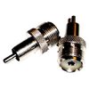
Does anyone know the name of this connector? Thanks !!11.jpg
 

That is a proprietary connector and "ducky" - they should have a side mount cover for a hole that allows for a Motorola (Car Antenna) style plug.

Else you will need to find a MM threaded bolt and nut to operate - the SWR loading on the whip itself is similar to a helical wound continuously loaded antenna - limited output range. You don't have a shield you can use with that - at least not without having issues in making it work.

Seriously? No, to using that threaded socket...because the Ducky was loaded (read matched) to mate with that type of impedance matching network. So you have limited options for finding a replacement - because as you held the unit your hand capacitively became the counterpoise for the ducky - you become part of the antenna.

The WT was made with a matching network that although less than ideal - worked because of the 4 watt output and the necessary "adaptation" the WT used in a loading network and coupling system - to make it work as well as it did for that era. IT should have a knockout or cap over a plug that looks a lot like a Stereo Phono plug like your older home stereos used - that plug uses this adapter...
MotorolatoSO239.jpg

The knockout plug was for a more universal (approx. ~72 - 75 ohm impedance) Motorola to SO-239 style adapter that at least let you hook up an CB antenna to it. You use an adapter like above - clumsy - yes, but it, the plug, is tapped at a spot on the W/T's TX output network that allows you to use this Phono to SO-239 adapter and provide a better efficiency connection for an external antenna.

You can also wire up a "HELP" magnet mount antenna that is for "help radios" - they have limited use but better range - but nothing compared to a more dedicated CB antenna that uses the stiffer 50 ohm coax versus the smaller coax the help antenna - at least it let's you mount that "help antenna" outside on top of the roof. Again they use that phono plug on the WT if it came with one.

Some even used a power plug coaxial connector like a power plug so I won't steer you down that road unless I know where you're going with this one first.
 
  • Like
Reactions: Wire Weasel
Thanks H Andy. Yes I know about the ant. jack on the side and have some of those adapters on hand. Still wanted to know about the Duckie Antenna type for portability improvement. I've done more research and it is appearing to be a Motorola MX Connector. I can then get a MX to BNC Adapter and then will probably get the 27" Cobra HA-TA Telescopic ant. that is BNC. All reviews say it doubles the range over the Duckie which makes sense.
 
Don't they usually use a BNC connector for rubber duck antennas? I can't tell from your picture if it has the twist lock on the sides?
Yes Ratt some are BNC but this one is not. After more research it is looking like it is a Motorola Type MX connector. Thanks !
 
  • Like
Reactions: TheRATT
If anybody cares or wants to add to their notes, this antenna type (8mm threaded stud) turns out to be a Bendix King design as is simply called a Bendix King connector. And there are no adaptors made for these by anyone. BK even went all O.E.M. on this and the stud additionally has a oddball thread pitch of .075
 
  • Like
Reactions: TheRATT
Does the connector look anything like this on the bottom?
EXH-160-SFU.jpg
 
If anybody cares or wants to add to their notes, this antenna type (8mm threaded stud) turns out to be a Bendix King design as is simply called a Bendix King connector. And there are no adaptors made for these by anyone. BK even went all O.E.M. on this and the stud additionally has a oddball thread pitch of .075

Thanks for getting back with us on that.

Still a few questions but nonetheless the matter seems to have been resolved.

Found several HT units from the CB era that come with a loading network that pretty much keeps the antenna - even if it's gone, from causing a poor or high enough SWR issue. The thing won't radiate well and you can damage the final in the unit when you're antenna is busted, but the design of the pi-network and the loading used makes it last longer in a poor SWR condition than most radios can withstand.

In my research to find the whip portion or even get an idea of how to find replacements - I was met more with "Why do you need to when you have an antenna adapter?" The adapter itself isn't a true adapter, it's simply swaps one connector to another type that mates with a SO239/PL259 arrangement - not necessarily a "best match" condition because the Motorola itself isn't made for 50 ohm.

So really the thing doesn't need to match more to a specific impedance more than just trying to take the impedance the output final "is" in the system and just transfer the energy to the antenna

So it's more of the transfer or loading of one to the other so these networks are not as "tight" in transformation as many typical "Dedicated" mobiles and bases do.

Hope this helps you.
 
  • Like
Reactions: Niceguy71
My Realistic TRC-207 walkie once used that same antenna. I swapped that connector out in favor of a female BNC. For a CB talkie, any other connector is undesirable IMO, including those antennas that are fixed. I like to mod those whenever practical with a BNC connector too. Particularly if the original fixed antenna is broken. That mod covers all choices, and as a portable I can still use a BNC Ducky for close work or my BNC Cobra HA-TA telescoping antenna for greater range. If you decide to install one, don’t forget to ground the outside portion of the BNC to chassis ground. A fixed antenna or a single conductor stud antenna like the one you have only deals with one connection. That will be your center pin connection on the BNC. I also tune the final stage into a dummy load upon completion. A very satisfying upgrade. Notice you won’t find too many newer 5 watt CB walkies without a BNC for good reason..
 
Thanks for getting back with us on that.

Still a few questions but nonetheless the matter seems to have been resolved.

Found several HT units from the CB era that come with a loading network that pretty much keeps the antenna - even if it's gone, from causing a poor or high enough SWR issue. The thing won't radiate well and you can damage the final in the unit when you're antenna is busted, but the design of the pi-network and the loading used makes it last longer in a poor SWR condition than most radios can withstand.

In my research to find the whip portion or even get an idea of how to find replacements - I was met more with "Why do you need to when you have an antenna adapter?" The adapter itself isn't a true adapter, it's simply swaps one connector to another type that mates with a SO239/PL259 arrangement - not necessarily a "best match" condition because the Motorola itself isn't made for 50 ohm.

So really the thing doesn't need to match more to a specific impedance more than just trying to take the impedance the output final "is" in the system and just transfer the energy to the antenna

So it's more of the transfer or loading of one to the other so these networks are not as "tight" in transformation as many typical "Dedicated" mobiles and bases do.

Hope this helps you.
Hi HA .... No not really. You seem to be giving answers to questions that I did not ask - both times - but I appreciate your interest anyway friend.
 
My Realistic TRC-207 walkie once used that same antenna. I swapped that connector out in favor of a female BNC. For a CB talkie, any other connector is undesirable IMO, including those antennas that are fixed. I like to mod those whenever practical with a BNC connector too. Particularly if the original fixed antenna is broken. That mod covers all choices, and as a portable I can still use a BNC Ducky for close work or my BNC Cobra HA-TA telescoping antenna for greater range. If you decide to install one, don’t forget to ground the outside portion of the BNC to chassis ground. A fixed antenna or a single conductor stud antenna like the one you have only deals with one connection. That will be your center pin connection on the BNC. I also tune the final stage into a dummy load upon completion. A very satisfying upgrade. Notice you won’t find too many newer 5 watt CB walkies without a BNC for good reason..
Well you know Sunbulls .... I never thought of replacing the connector altogether as you suggest. That sounds like a jam-up awesome idea. I don't know what kind of major surgery that will be on this G.E. but I am going to take a look at doing that for sure. Thanks for the great idea !! I definitely post back here if I do that
 
Hi HA .... No not really. You seem to be giving answers to questions that I did not ask - both times - but I appreciate your interest anyway friend.

You're welcome, I took it more like a lesson on when you remove the little constraints of getting the signal from the radio to the antenna. Like impedance "bumps" each connector and connection point along the line induces - what you have left is a considerable amount of freedom to produce, provide and radiate a signal from a known impedance into another "expected" impedance and you get rid of the required impedance constraints the conduit to connect them both is. That is where the HT can excel at efficiency in radiated signals where other more dedicated systems, if not provided for, will fail miserably at.

The HT design is interesting, it's self contained, so they only needed to make a network that kept the environment from reflecting back to the final.

It also has a uniqueness that being portable for what it is, didn't need all the filtering - FCC didn't enforce the filtering issue on them at first, but later, it became necessary. It's unfortunate - although later models provided it because people used them for base stations too - which the FCC had to initiate another stage or process of having the radio makers install better filtering in later model years...

The output network of a final - the impedance is pretty low, like only several ohms, on up to maybe 25 ohms at best.

So you (the maker) only need to concern yourself with the impedance the attachment of the whip, ducky or doorknob, becomes for the antenna - and knowing it's own impedance you simply design the network for it, not "just 50 ohms like everything else" because of the connectors and cabling support had another type of impedance which added to the problem/.

So since radiation resistance is pretty low for shorter antennas like those used in HT's - you have heavy capacitance as "seen" by the final - but remember you don't have that 50-ohm impedance constraint - just do up a network for that "range of impedance" the antenna appears as to the HT. It will use a given amount and the rest will take care of itself. It's not ideal, but it does work - not an ideal "tower of power" but the longer whips and dedicated systems made the HT do pretty well for what little power they actually had.

It was the SWR thing I'm still trying to get my head around. I'll never really know if I got it right or not...

It looks as - even if the lower the impedance the HT can use, in the system, the more it relies on the radiation and open circuit resistance factor (those caps inside in the PI-network) - hence the more the open circuit the thing is, the radiation resistance even as low as it is, as seen by the final in the HT, can be overcome by the loading it uses inside to help transfer the signal to the outside and in doing so- keeps the SWR issues from becoming a big deal inside - by forcing the SWR reflection seen by the final as a higher impedance than the outgoing signal is But as it comes back into the system, the reflected signal just "dumps" into the output capacitance just past the coil - the cap(s) appear as a dead short to it.

So there used to be a BIG argument in the USENET rec.radio.* groups that took this discussion down, pared it down - nearly to the atomic level - about how output networks absorb the energy - and their mechanisms that did this process. For in light of the HT - that network issue was specific to the device, not to the system - for it was a "unit" as system in itself - not something that you had to make accommodations for, like in the cabling and connections and their impedance requirements to get the signal out to radiate and receive likewise.

So sorry for the long letter - but your situation is unique for that this equipment was made in the past for "portable" and yet even in our current system and frames of mind, we can use those lessons learned from such time, and a simple system and apply it out in the real world.

But most of all, enjoy the radio - a piece of history, and have a great Xmas to go along with it.
 
Andy I may have put it differently . I doubt I'd have done it better.
The external , generally an RCA connector is normalized to/at 50 ohms. The antenna output ? Not so much.

The usual center loaded "Rat Shack" portable whip really wasn't so bad as far as radiation resistance.The reactance was capacitive of course but the resistance was on the order of 36 Ohms. Not so for the random whip on smaller HTs . In this case the matching network didn't so much match the several ohms output impedance of the output transistor to the low radiation resistance of the short antenna as provide a near short for reflected energy thereby protecting the collector/emitter junction.
A quick look at the 2SC1730 data sheet (very common output transistor) explains a lot. .05A @ 15V max and between 1 to 3 ohms output impedance.

So , Andy, differently, not better (y)
 
.... stuff ....

.... more stuff ....

Most of this is above my pay rate so forgive me if this is stupid. If I'm reading this right in these walkie talkies they tuned the output of the radio to match the antenna used instead of tuning the output to the standard 50ohms for use with commonly available antennas, it seems to me that the radio would now be married to the specific antenna the manufacturer put on it. I'm wondering how this would effect things if you mod the radio with a BNC as sunbulls suggested.

So if you were to replace the antenna connector with a BNC would it be necessary/recomended to make any changes to the output stages of the radio for use with different antennas?


.... I also tune the final stage into a dummy load upon completion. ....

I feel that this may be the answer to my question so, does this relate to what I referenced above? the word "tune" can mean a lot of things in this hobby.
 
Last edited:

dxChat
Help Users
  • No one is chatting at the moment.