• You can now help support WorldwideDX when you shop on Amazon at no additional cost to you! Simply follow this Shop on Amazon link first and a portion of any purchase is sent to WorldwideDX to help with site costs.

OVER 130% MODULATION!!!

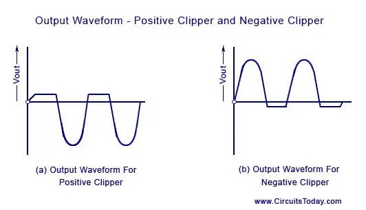
Audio compression uses positive peak compression; not negative peak compression. IIRC, the AM Limiter is actually a positive peak limiter type of compression, which means that once the gain reaches a certain threshold compression takes place at a 4:1 ratio. .

Robb -
please explain your thinking on this. Like Exit thirteen, I always believed that audio compression affected both positive and negative peaks. A typical AMC circuit samples the output of the modulator and feeds it to the amc circuit. This circuit controls a transistor which shunts a portion of the audio input to ground when modulation exceeds 100%. This transistor will shunt both the pos and neg portions to ground, so where do you get this "positive peak compression" thing ?? Just because the dc blocking diode only lets the positive peaks be sampled is meaningless. Since the audio signal is symmetrical, if the dc block wasn't necessary the negative portion (or the whole signal, for that matter) could be sampled with the same result.

To me, audio symmetry is the key here. Regardless of how it looks on a 'scope, if the audio loses symmetry, it will sound "muddy", as if something is missing. If you're going to negative peak limit, it should be done after the modulator. This way, when the signal is demodulated, the audio will be in symmetry and will sound "right".
73s.

- 399
 
Unit 399,

I like the way you worded the way an AMC circuit works. it instantly made me start thinking of ways to only allow the AMC to shunt the negative peaks.

like, the variable AMC now becomes a variable negative peak compressor.

hmmmm...
LC
 
unit_399:
The AM Limiter affects the positive peaks before it affects the negative peaks. Pull it out and positive peak will go over 100% before the negative peak does. I suggested - if you read the whole thread - you will find that I said pretty much what you did, that to affect the negative peak it should be done in the AM Regulator circuit and not the audio circuit.

I also did say that audio compression - speaking in general terms - is not correct because it acts more like a limiter (which by definition 'limiting' uses a 4:1 ratio with a fixed 'threshold') by the way the radio's circuit was designed for. It isn't real audio compression in the sense that it can be tailored to soft/hard knee compression, variable ratios of compression, variable threshold, or with variable attack/decay times as a real compressor can do. Radios use a fixed limiter setting by design and effect. Cheap; but not the same quality as real outboard audio processing would work.

So some compression is added to the negative peaks by way of installing a diode in the AM Reg. Xit13 asked the forum how he did it at first, and I guessed it right. I mentioned an electrolytic cap in the audio circuit because most people do it that way. Xit13 also changed the resistor value (R228) in parallel with the diode in the AM Reg, probably why he went to 180% instead of 140% that he was getting before with the cap mod on the audio circuit alone. The standard NPC mod for this radio - as done in the popular sense - is to clip the AM Limiter out, put a cap on the audio circuit, and volt the final.

At least, that is what I can can gather from it all . . .

*EDIT*
Xit13 might also consider putting a 1.5k ohm resistor on the center lead of the AM Limiter, which should reduce the effect of the limiting action in circuit. From what I understand, it should raise the AM Limiter's (Q24?) 'threshold' point before limiting can occur. But since he is already seeing 180% modulation, I don't see why he would need to. I'd be interested in seeing if he could get 200% if it is possible; but he has done plenty already on this forum and his work is much appreciated. Fair question - though . . .
 
Last edited:
  • Like
Reactions: tecnicoloco
guy's I have been reading this mod since you all started it. I have done the R228 mod for over 15 years now on certain 148's and 2000's and it has always made the radio get up and sound a lot better . I have changed the value of R228 on a few also. never even brought this up because most forums you get bashed on for doing this mod by unbeleivers of changing any thing on the radio other thab the normal specs for the radio. I have always gotten good feedback on how much better the AM sounds on a radio doing this mod. never have told but a couple techs I know about it. keep up the good work Exit 13 and Robb. I have a 148 I run in my pickup ever so often and one guy I bought a magnum 3200 from swore up and down I was not talking on a 148 and the 1st thing he did when I picked up the magnum from him was he ran out to see what radio I was running in my vehicle. he wanted to know the mod and never did give him the info on it. he works on radios out of his garage at his home and has been doing his repairs there for about 20 years now.
 
Xit13 might also consider putting a 1.5k ohm resistor on the center lead of the AM Limiter, which should reduce the effect of the limiting action in circuit. From what I understand, it should raise the AM Limiter's (Q24?) 'threshold' point before limiting can occur. But since he is already seeing 180% modulation, I don't see why he would need to. I'd be interested in seeing if he could get 200% if it is possible; but he has done plenty already on this forum and his work is much appreciated. Fair question - though . . .

Robb, I have done this mod with the 1.5K ohm resistor before, but it doesn't give me the desired results. For this compression mod, I wanted to ensure that the AMC circuit was as original "bone stock" as possible.

LC is correct when he notes that the AMC circuit has a fixed resistor instead of a variable. This is only on the Madison and the fixed resistor is 10K ohms. Since the PCB has the components screened in for a diode and variable resistor (with all holes present to install them), I simply removed the fixed 10K ohm resisitor and installed the diode, and a 10K ohm variable.

Also, I plan on getting a 1uf, non-polarized polyester film or mica dipped capacitor to try on Monday. I will post the results then. I don't see why I can't achieve 200% positive peaks with 100% negative, and in all reality it would achieve a nice 2 to 1 proportional ratio of positive to negative.


~Cheers~
 
  • Like
Reactions: Shadetree Mechanic
This was snipped form the 148GTL schematic on CBTricks.
So, changing R228 from a 560 ohms to a 1.2k ohm resistor allowed more current to flow through D63.

Not sure how this affects the negative peak?

*EDIT*
OK; it is between the audio amp and the 2sc1419 AM Reg.
 

Attachments

  • R228.PNG
    R228.PNG
    79.3 KB · Views: 79
Last edited:
unit_399:
The AM Limiter affects the positive peaks before it affects the negative peaks. Pull it out and positive peak will go over 100% before the negative peak does. I suggested - if you read the whole thread - you will find that I said pretty much what you did, that to affect the negative peak it should be done in the AM Regulator circuit and not the audio circuit. .

The am limiter affects positive and negative peaks equally. The limiter is in there to prevent harmonic generation and bleedover. It's the negative peaks exceeding 100% that causes bleedover, so a limiter circuit that affects pos peaks first would be somewhat self-defeating. You have to remember that the limiter circuit response time is practically instantaneous (a few microseconds at most). So IF there was a difference between pos and neg peaks' response times, it would be so minuscule that you'd never be able to see it.
If you're suggesting that the mod should be done at the AM regulator (modulator). you are correct. Truthfully, since my interest is ssb, I haven't paid much attention to this NPC mod because it's an am-only thing. Maybe if I have the time, I'll check it out further.
73s.

- 399
 
Update:

I went out and bought a 1uf non-polarized mylar capacitor and installed it. My positive peaks are now approaching 210%, while keeping the negative peaks at about 90-95% currently. I was told by my neighbor and several locals that my audio tone did not change any, I didn't get mushy or muddy sounding, audio is still nice and clear. Will put up scope pics when I get some free time.


~Cheers~
 
  • Like
Reactions: tecnicoloco
cool!

that means that by the time you get all the way up to 10uF, you'll be doing 1000% positive modulation!!!
right? :LOL:


ok, couldnt help it.

are you having to adjust your AMC each time you change the cap value?

do you seem to be adjusting it by about the same amount?
LC
 
This was snipped form the 148GTL schematic on CBTricks.
So, changing R228 from a 560 ohms to a 1.2k ohm resistor allowed more current to flow through D63.

Not sure how this affects the negative peak?

*EDIT*
OK; it is between the audio amp and the 2sc1419 AM Reg.
What I'm gathering from this mod is that we're bypassing the speaker cap and dropping the audio across D63/R228/R194 junction. What this looks like to me is a parallel negative limiter circuit with slight clamping action. By changing the resistance we change what negtive portion the limit will happen at? I hope I didn't confuse myself with my understanding here, Navy electronics training is vague when it comes to actual applications of circuit theory. Just for adding to discussion, I was working on a 148/2000 style of board and it had this device that was able to control your positive and negative peaks to over 200 and limit the 100 on the negative side. This device also allows you to play with tube emulation, carrier and a few other things, I will let your imagination tell you what this is. Anyways what it did was bypass the AF amp and drop the audio on to the regulator which was isolated from radio VCC. The regulator drove the final however the driver was volted and resembled a tube modulator/PA setup if you may. Back to this mod, adjusting the resistor value, to me seems to control the limit "compression" happens at ie. the negative peaks. I wonder if placing a potentiometer in place of R228 and adjusting for the right negative limit be an option? I did the OP mod with changing to a 1K and a .47uF Mica cap and was able to adjust for 180 to 200% positive peaks, however the negative never reached the reference line(100%). It was more like 85 to 90% and acting like it was in severe cutoff. The audio was muffled and I had to back the mic gain down alot to keep the positive peaks from flat topping. I theorize the value of the cap is not as important as the value of the resistor in this mod. The cap provides DC isolation and passes the Audio(AC signal) over to the regulator. The value of the cap should determine the frequency of audio being passed or coupled. My question is shouldn't we disconnect C174 so that it doesn't provide alternate audio from trying to also reach the regulator? Anyways, great discussion, I hope I added something positive to this post while limiting the negative peaks...LOL
Virtual Labs - Dayalbagh Educational Institute - Agra - Theory

The first link reminds me of this circuit, parallel negative limiter. The second link is what my waveform looked like after this mod.
 
  • Like
Reactions: tecnicoloco
Not trying to rock the boat, it maybe one of those gadgets. I like to try to achieve the same results using something else. Its an awesome device and sounds great but trying to figure out how to achieve the same results is part of the fun.
 
Final results right here. This is done on my President Madison, using a 1uf non-polarized metal film capacitor and a 1.2k ohm resistor at R228.


First pic is the 2W carrier, non-modulated, on my scope.

IMG_20140725_233252_427_zps41c38f27.jpg


Second pic shows the 2W carrier modulated. Positive peaks are about 220%, with negative peaks around 80% with no flat-topping or distortion.

IMG_20140725_233722_502_zps0c0d5f37.jpg


The locals rave about the audio quality on AM. Results may vary a little, depending on radio, but every radio I've done this mod on so far has had no less than 180% positive peaks when the AMC was properly adjusted, so it's a pretty safe bet that 180% positive peaks would be possible on just about any radio that uses this chassis, such as the Cobra 148, the Cobra 2000, the Uniden/President Grants, and the Uniden/President Madisons.

I do have a Uniden Washington that has the single conversion AM/SSB chassis in it that I can try this on, don't think it would be much different.


Hope you all enjoyed! (y)


~Cheers~
 
Last edited:

dxChat
Help Users
  • No one is chatting at the moment.
  • @ Wildcat27:
    Hello I have a old school 2950 receives great on all modes and transmits great on AM but no transmit on SSB. Does anyone have any idea?
  • @ ButtFuzz:
    Good evening from Sunny Salem! What’s shaking?
  • dxBot:
    63Sprint has left the room.
  • dxBot:
    kennyjames 0151 has left the room.