• You can now help support WorldwideDX when you shop on Amazon at no additional cost to you! Simply follow this Shop on Amazon link first and a portion of any purchase is sent to WorldwideDX to help with site costs.

Parallel connection of Plate Transformers

Naysayer

Well-Known Member
Mar 6, 2020
183
141
53
New York
Not as simple as I thought.
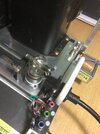
Preparing to connect 2 Heathkit 54-30transformers: Single Pri/Sec windings for 110v to 1800v at 400mA with a CT. I need more plate current. The 54-30's are potted with no markings regarding phase (direction of windings around core), I don't have an oscilloscope but found a few vids on determining phase with an analog meter & a small battery. Hope I'm mistaken and someone will reply: just hook'em up phase unimportant. I'm afraid of ruining the transformers and making a smell my wife will remind me of for years to come. I ordered SHV fittings, proper wire and built a safe but small enclosure for the second unit. Want amp to work without 2nd unit as it does now.
I thought I could use a second AC plug for the 2nd transformer tapping another AC outlet. Need to re-think that despite polarized plugs.

Still processing my resort to a COR keying board. Passed through the Denial stage and inching toward Acceptance, get on with my life Thoroughly defeated on that count but it will work, maybe add a relay.....feel better about it. Not much I can find on how the newer Yaesu's key external amps and joined the FT-891 group but mostly plug n play tales. It seems to be a pulse trigger but I'm >$100 on keying so next move must work.
++++++++++
EDIT: Found a "Transformer Dot Convention Finder" kit. PCB only $10 with parts list uses a 555 Timer to inject signal. It looks simple fast build, useful tool and price is right. See:

https://www.pcbway.com/project/shareproject/Transformer_dot_convention_detector.html

2nd EDIT: 1993 ARRL Handbook's section on parallel transformers (only 3 paragraphs & 1 diagram) makes no mention of phasing (p6-2). It does suggest using a 3rd transformer's CT secondary to equalize the 2 Secondaries being combined with the 3rd Primary left unconnected.

Maybe I'm making an issue where there is none. I have a choice btwn rabbit hole and just hooking'em up.
 
Last edited:

Following 2 paras are cut & paste from other forums that address my Rabbit Hole option:

"You can dependably connect 2 AC sources IF they are synchronous or can be made synchronous assuming they are at about the same voltage level and can supply matching currents of similar impedance.

Fuses, low-ohm resistors and high-current inductors may allow for slight shifts in phase and voltage. Separate AC sources need to come from the same breaker panel to have any chance of being in phase. In practice, it can be very difficult because you need to synchronize your two power sources. If they're out of phase, you'll find that the power output is dramatically lower. If your sources are 180 degrees out of phase, you'll actually see 80V across your load rather than 100V or 120V. You actually can make it so the load sees less power than it would have without the second AC source"


So, I can start with a really low voltage on primaries and see if one connection yields a higher output than the other. There are only 2 possibilities so if there is a seeable difference I could safely presume that is the in-phase connection.
 
Last edited:
My 1st homebuilt Hi-amp 12 volt supply used two transformers in parallel. The transformers were identical. The secondary had a black and a red wire, so I connected like colors together and connected an AC voltmeter across them. The primary wires were both the same color, so I connected them together and hooked them up to the output fo my variac. Set the variac to 30vac or so and turned it on. Output voltage of the variac dropped to zero, so I shut it down and switched the primary connections. Turned the variac on again, and it held steady. Turned the variac output up to 110vac, and the voltmeter read 18vac like I expected.

If you don't have a variac. , just hook the transformers as I described, and apply 110vac. You'll know in a heartbeat if they're hooked up right. If they're not, just shut down right away and change the primary connections and you'll be good to go.

- 399
 
Last edited:
The old "100-Watt bulb in series" test will work. If you get the phase backwards, the transformer becomes a low-value resistor and the bulb will be bright when power is applied. The bulb limits current to a safe value.

And if you get the phase correct between the two secondaries the bulb will be dim or dark.

Putting them in series is different, If you get one of them reversed, you simply get zero Volts.

The "octopus" in my avatar was the ultimate test for getting parallel windings reversed. It would show a reactive circle if you had the hookup right, and the straight line of a resistor if you had one of them reversed.

Quicker than the bulb-in-series hookup.

73
 
Thank you for the helpful Replies. I'll need to temp disconnect the mounted xfmr to make the low voltage comparisons. The Primaries don't matter? Appears I can pass on the Dot Convention Tester as I can't justify it now.

My request for help on the FT-891 Keying issue got a detailed Reply about how to analyze the radio's keying circuit through the 8 pin DIN jack with a 9v battery and a meter. I will re-post his suggested procedure in a separate thread (after I get his permission and try it myself) to make easier to find for anyone else troubleshooting the FT-891 keying circuit.
neil, NYC
 
The Primaries don't matter?
How the primaries are connected dictates how the secondaries will match.

If you know which wire on a winding is the start, and which is the finish you can phase them that way.

The by-gum-and-by-gosh method is what I rely on when there is no clear color code to go by. The Antek transformers we rely on more and more use one color for a winding's start, another for the finish. The HV windings wired in series on this one are yellow and white. Simplifies the hookup. Parallel puts white to white and yellow to yellow. The series hookup here is white from one winding connected to the yellow wire from the other HV secondary.

5V5c1N.jpg


A more typical color code makes both wires from a secondary the same color. Teasing out how it gets phased with another winding becomes a chore.

73
 
Last edited:
How the primaries are connected dictates how the secondaries will match.

If you know which wire on a winding is the start, and which is the finish you can phase them that way.

The by-gum-and-by-gosh method is what I rely on when there is no clear color code to go by. The Antek transformers we rely on more and more use one color for a winding's start, another for the finish. The HV windings wired in series on this one are yellow and white. Simplifies the hookup. Parallel puts white to white and yellow to yellow. The series hookup here is white from one winding connected to the yellow wire from the other HV secondary.

5V5c1N.jpg


A more typical color code makes both wires from a secondary the same color. Teasing out how it gets phased with another winding becomes a chore.

73
I'll use a 3rd transformer to place low volts on primaries. The internal xfrmr connects to HVPS board with 1.5' of 22awg HV wire. I'll need two, 5' lengths of HV wire to connect external xfrmr secondary. Can I use the same 22awg HV wire or does the 4' difference in wire length justify 20awg?

The FT-891 keying issue has consumed my radio time, Testing suggests damaged radio. Not the end of the world, everything works except keying circuit. Yet I'm puzzled how the Tetrode board's low volt/current keying circuit was enough to damage radio: 12v at 100mA doesn't seem like enough to damage anything. That's the way it is, Acceptance move on.
 
Follow-up Question on Parallel Polarity of transformers: If the Primary parallel connections determine Secondary polarity, is it correct to conclude that it doesn't matter how the primaries are connected? As long as the secondaries are correctly adjusted thereafter?
 
The polarity you feed into the primary determines the polarity of what comes out the secondary.

The transformer won't care which way you do it, so long as primary and secondary are phased to each other properly.

73
Thanks for verifying that. Parts begin arriving today. I'm tempted to power the external primary from a separate AC outlet (polarized plugs/reduce wires), but I can decide the pro's & cons later.

Xfrmr secondaries will join at the HVPS board (Nomads) where 2 resistors (ww 7.5R 5w Vishay, 1%) feed the FWB diode stack. Placing 2 identical resistors btwn panel mounted SHV connectors and diode stacks looks like a good idea. Alternative is feeding both xfrmrs through the board mounted resistors. I've noted those resistors take a real beating there even with the soft-start.

I want amp to work without external xfrmr.

It's cold for April in NY City today. Trees are sprouting looking nice again.
neil.

PS: I found the 2 holes on the diode-stack side of the input resistors (hvps board) to be perfect for mounting the 2 additional resistors vertically. Almost like they were there for that purpose lol.
 
Last edited:
Yes, I see now. It's obvious when the leads are switched. Thank you everyone for running this down for me. Transformers separately are only .5v off from each other on my cheapo VOM meter (Yet, it is the best of the cheapo's lol)

Morning after: Transformers working in parallel when powered by a small transformer of unknown dot convention. Edited several times, this issue was/is confusing to me. Transformer Phasing, it's a lot to keep track of but I think I got it now.
neil NYC
 
Last edited:
I finished the wiring. I replaced all wiring from the IEC320 jack thru soft start to transformer primaries (chassis mounted xfrmrs) with 12 gauge. Picked up about 25-50mA plate current from that alone as I used smaller wire when I began years ago. I placed the SHV jacks in corner top of chassis (pic). Vacuum relay linkage kept jamming when mounted upside down (inside chassis) so I moved it onto the top.

Tracking AC polarity from mains to transformer primaries was tedious. I have not yet tried running both xfrmrs. The new 12 gauge alone added to the plate current readings on work table (available AC current is limited at table). I'm still a few days from trying both xfrmrs together using a heavy duty AC outlet near operating location.

Still deciding external xfrmer primary connection: Separate AC outlet or from amp chassis (more wires I'd like to avoid). I don't think it matters if the external xfrmr is powered from a different Circuit Breaker as long as the AC plugs are polarized and I'd verify outlet wiring for Hot/Neutral first.

This was more complicated than I first thought.
 

Attachments

  • SHV jacks.JPG
    SHV jacks.JPG
    1.4 MB · Views: 14
Parallel Xfrmr successful! Easily >1kw :giggle: into DL. That straining noise/hum from being underpowered is completely gone. Tomorrow I'll try the 20A Air Conditioner outlet near operating location after I seal it up again.

I fused the external Xfrmr ("X") Hot lead to primary. Began with 2A and got to 7A where it finally held. I am sequencing the power-On and Off to the external X so it is energized after the Tet Board warm-up cycle completes and before I turn amp Off. Otherwise, the external X feeds AC power into the rest of the amp (thru the on-board plate xfrmr!). Seemed unnatural when I first saw it happen.

Time to address the T-R relay switching issue.

Thank you everyone for the advice on connecting 2 plate xfrmrs. Tomorrow should be fun.
neil, NYC
 

dxChat
Help Users
  • No one is chatting at the moment.