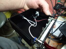
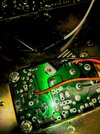
I haven't found anything on this particular mod in here, I apologize in advance if Ive missed it. I have a 142gtl, it was my first radio. It also has many extra channels added and scattered. I am trying to connect a PLJ-6LED 6 digit counter. I am having issues with power and signal. Keep in mind, I am not an electronics engineer. I picked up my signal from TP1 and the ground beside it. I used a 100 ohm resistor on my signal side. The counter does display frequency in receive and transmit. I pulled my power from the power supply (13.8v). Installed an IC7808 voltage regulator in my external enclosure with the display. 2 issues... After making the connections at TP1, IC4 bit the dust. Replaced it and only lasted a few minutes (could be a bad part, or my ignorance). I have checked everything I have found to check, Voltage on pin 2 of IC4 should be 2.95v, I have 6.6v. Pins 5 and 6 should be 1.9v, I have 1.1v. I have since recapped, no help. Also with the frequency counter plugged into the radio, upon power up I have a very loud squeal. With the counter powered from a bench supply, seems fine. Any help would be greatly appreciated.
-
You can now help support WorldwideDX when you shop on Amazon at no additional cost to you! Simply follow this Shop on Amazon link first and a portion of any purchase is sent to WorldwideDX to help with site costs.
-
The Feb 2025 Radioddity Giveaway Results are In! Click Here to see who won!
Cobra 142GTL frequency counter
- Thread starter Spams24
- Start date
There are four electrolytic caps around IC4, the TA7222P audio amp. Any chance one of them has the polarity reversed?
The squeal is usually from a ground loop. The ground side of the counter's power should go to the ground foil where the big filter C134 negative lead is soldered. The ground side of the signal input should have a disc capacitor between the ground wire and the ground foil in the PLL section. A .001 uf disc cap works okay. Passes the 34 MHz RF signal, but not the audio-frequency noises.
Just make sure the counter pc board is totally insulated from the metal chassis.
73
Can't hurt. The 7808T should be isolating any upstream noise on the power lead from the radio side. We saw a couple of these that were installed with the PLJ bolted to the chassis metal. Caused big-time ground-loop squeal issues. Insulating the screw hole grounds on the PLJ with plastic mount brackets fixes that.Would a diode do me any good on the power side?
73
Heres what Ive got. The white wires are shielded teflon. My freq side has the inf cap on the ground side and a 100 ohm resistor on the signal side. The power feeds straight off the switch, Had the ground tied to the power supply by the black wire there. Moved my ground to the negative side of C134, no change. The 7808 is isolated from the housing inside with the plj. Removed the face and isolated the plj, no change. I know Im doing something wrong, I just dont know what.
Don't know if it makes a difference, but I adopted the habit of putting the 7808 at the power supply end, and running the output to the counter. Soldering the regulator's metal tab to the ground foil on the radio circuit board seemed to work best. The ground foil provided enough heat sinking. Seems like putting it into the enclosure should do the same thing, but I haven't tried it that way. The data sheet's advice to use a capacitor on the regulator's input pin is no biggie when it's soldered to a ground foil a fraction of an inch away from the big filter cap. Shouldn't need to put a cap on the regulator's output pin, there's a 47uf on the power input on the PLJ.
Just why it interfered when it was inside the radio isn't clear at all.
73
Just why it interfered when it was inside the radio isn't clear at all.
73
Nomad mentioned a ground loop. Sounds like you have one. You have a ground with the teflon signal wire at the VCO, and you have a power ground. If the two grounds, signal and power in the counter, are tied together in the counter, it is the equivalent of inserting a big loop of wire between the supply ground and the VCO ground.
The power requirements of the counter cannot be too significant, so could you move the power ground to where the signal ground is, or remove the negative power lead entirely and let the shield do that?
The power requirements of the counter cannot be too significant, so could you move the power ground to where the signal ground is, or remove the negative power lead entirely and let the shield do that?
Yeah, like that. I just noticed the 3-conductor 'phone' jack for the external display. Does the jack have an insulated plastic bushing? If not, a metal bushing will be at chassis ground. Bridging the circuit-board ground to the chassis ground nearly always produces ground loop problems. This radio uses a so-called "floating" ground for the chassis, with no DC connection between the power supply's negative side and the metal chassis. A jack with a metal bushing would bridge the chassis to the circuit-board ground.Kinds like this?
73
The connector in the back is a 6 pin molex, all plastic. The ground loop through the counter could be the issue. Got fed up last night and put a 9v battery tray in the back with a power switch on the front. Havent tried it yet. This counter was intended to be just for this 142. In the middle of my chopping holes in the counter case, a buddy talked me in to buying a President Washington from him. So I guess it worked out as I should be able to use it for both radios this way. I do still have some voltages that are out of spec, mainly on the ta7222. Still havent figured out why it has 6.6v on pin 2.Yeah, like that. I just noticed the 3-conductor 'phone' jack for the external display. Does the jack have an insulated plastic bushing? If not, a metal bushing will be at chassis ground. Bridging the circuit-board ground to the chassis ground nearly always produces ground loop problems. This radio uses a so-called "floating" ground for the chassis, with no DC connection between the power supply's negative side and the metal chassis. A jack with a metal bushing would bridge the chassis to the circuit-board ground.
73
dxChat
- No one is chatting at the moment.
-
-
-
@ Geoexplorer69:Coax question. I just put up a new Sirio monsoon base antenna with 100’ of rg8u coax testing with myMFJ antenna analyzer shows 1.4 swr at 26.965mhz and a 1.1 at 27.405 mhz . When I checked the ohms it’s steady a 30 ohms across the entire bandwidth.
-
-


