Okay, not sure about the color code, but if the mic audio went low AFTER adding the cap to pin3, try removing the .01 cap from pin3 to ground. Thanks for the info, can never have enough sometimes. Sometimes a pic can mean everything.
Hello Cable Guy,
Hope you were able to rest up a bit.
No, the audio had gotten low after I figured what was causing the growl and taking off the solid grounded buss wire from pin 3.
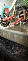
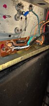
All I can describe is the radio's mic jack was loose and by placing a mic on and taking it off the connector a few times worked the wires off behind the mic jack.
I originally wired the white audio wire onto pin 1 which should had been the shielded wire. And I soldered the shield to pin 2 which should had been the white audio wire on this pin. I did get the green wire, the PTT correct on pin 3.
The funny thing is, it seem to work like it should, until later on the growling sound started coming into the receive. At one point I soldered the solid buss wire to pin 3, the PTT thinking that will fix the growl. For a short time it did help, and the radio didn't go into transmit for some reason when it should had because ptt and ground causes the radio to go into transmit as designed.
After I figured what I think is the correct wiring, and did the rewiring, the transmit audio didn't work. That is when I was trying to by-pass the echo board. In doing so, I burned out the echo board and I believed I may have weaken a component in the audio chain. Because after I figure how to by-pass the echo board, the audio worked but was low as described.
I just recently added the .01 cap to pin 3 PTT in hopes that for some dumb reason it would satisfy the low transmit audio???
This is what started this whole ordeal. I know the difference between pin 1 and 2, but some how I mixed them up when soldering them on.
Now by placing the shield on the audio pin and audio onto the shielded pin, perhaps the shielded wire on the audio pin no. 2 had shorted something in the audio chain, I just don't know.
It had to be what had done by mixing up the these two pins or something I done when trying to by-pass the echo board?
I am at my wits' end, but I haven't given up, There has to be something that is causing this issue?
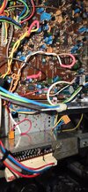
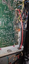
Just discovered something else. There are three wires coming from the main board.
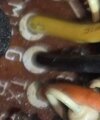
These three wires are orange black and yellow. They originally connect to the echo board.
The yellow wire is mark as mic and the black is marked as ground, and the orange is marked as TX.
For some reason there is -6.91 volts on this black wire. I first touched the black wire to the aluminum wall plate that surrounds the main board. As soon as I made the connection, the frequency display blanked out.
Of coarse I removed it immediately and the counter display came right back. But this black wire is suppose to be ground. Why would it short out the display by connecting it to ground.
I appreciate your patience, thats for sure.
RF Krazy


