• You can now help support WorldwideDX when you shop on Amazon at no additional cost to you! Simply follow this Shop on Amazon link first and a portion of any purchase is sent to WorldwideDX to help with site costs.
  • The Retevis Holidays giveaway winner has been selected! Check Here to see who won!

Galaxy Saturn growling noise from echo board

I would try operating the radio without it's on-board power supply. Leave the unit unplugged, the power switch OFF, and connect a good 13.8 VDC supply to the Red (+) wire going from the on/off switch to point # 22 on the main board, and the (-) supply wire to a suitable ground point. If the growling noise goes away, then the noise is being generated by the power supply. If the noise is still there, at least you've eliminated the supply as the culprit.

- J.J. 399
Hello Unit_399,

Sorry I had missed your post.

Great idea about by-passing the eternal supply. If it had a 12 volt connection on the back I would had tried that because the thought did crossed my mind when Nomadradio first told me about checking voltages and mentioning the supply.
But I will admit I did not think of connecting external voltages across the switch and such.
Again great idea and thank you for helping. What a pickle I have gotten myself into.

RF Krazy
 
Yeah, I bypass it like you tried to do it, using jumpers if i want to keep the connectors for reinstalling later. You are creating a mic/ptt pass-thru with the jumpers. Let me check my notes on that and pour over the voltage readings.
Hello Cable Guy,

This morning I figure the out the wiring as far as the audio in and out.
I simply took an ohm meter to the pin 2 (audio) of the mic jack and then probed around on the echo board connections until I had continuity. Then study how it was connected, along with the PTT in the same connector housing. I assumed the other wire (Output) and I just happen to be correct!

Orange and yellow being PTT. White being mic input and brown being mic output that is connected to the echo board. The black wire between the brown and yellow wire is ground. There was a CUT/snub gray wire between the yellow and the white wire but I have no idea what it was or if it was ever used.

So I have the audio working with by-passing the echo board entirely.
I am told the audio is not that loud though.

The echo board probably has a bad transistor or a a bad diode on board I am guessing.

I have found TR32 AMC shunt switch cut with a diode not far from the circuit also cut on the main radio board. Not sure what the diode did in the circuit but I will be looking at the schematic to try to figure it out and then replace it.

Now to figure out why the audio is low is another question. Perhaps replacing TR32 and that Diode will give it a boost. I really don't know.

Thank you NomadRadio, Cable Guy and Unit_399 for helping.
It really makes a difference when someone is there lending a hand.

73
RF Krazy
 
Hi RF Krazy, I have been busy this week replacing steering and suspension parts on my work truck, the lower ball joints are atrocious as I have to drill out the rivets, and I hurt all over lol. Your voltages seem fine now after figuring out the ground. Tr32, if the one I'm thinking, is sometimes clipped for modulation, being the mic line shunt, preventing the limiter from acting upon your "I got down" moments. Clipping it shouldn't make your mod lower, but peak higher possibly distorting if not careful with your mic gain.

Now, I often remove the echo board when widening the audio bandwidth as it's bandwidth is rather narrow and becomes a choke point, but if louder is what you want, I would replace it as a bit of echo seems to increase your average loudness, or so i have perceived.

Okay, I have to get back to the grind, I will check in later. Good luck!
I appreciate you replying back.

I thought after what I had mentioned above, everyone abandoned me! I figure being truthful always got me through life so why stop now!

Working on your steering and suspension as well as ball joints can be hard work for sure. I think my 79 Blazer had bolts holding the ball joint in.
Yeah what a pain drilling rivets. Specially if you can't get the drill where you need it. I guess a 90 degree drill could help but they can be a pain to work with too. I feel for you. I have skinned some knuckles in my day and probably will continue to.

As for the limiter TR32, I rather replace it. I looked up 2sc945aq and it can not be found. When dropping off the letter Q on the end it can be found. So I suppose I could just order the 2sc945a and it will probably be the same part, but honestly I don't know.

I have the echo board removed. Since you said that you have yours removed for a wider bandwidth, I will keep it out and see how it goes.

For some reason or another, I am told my audio is lower then it should be compared to my signal.

I believe I have blown or weaken something in the audio chain.
I have also found D68 diode clipped. I will be replacing it as well.

I am wondering it I could had weaken IC4 the Op amp that you had told me to check the voltages on?

Well again thank you for replying back. I hope you are resting up while you are able.

RF Krazy
 
You can use a 2sc945, it's quite common in many radios, if you have a parts donor. Have you tried another mic? Does it growl in tx also? Or just low mod on tx?
 
Hey I'm thinking off on a tangent here, tell me, how did you set bias on the new finals?
Hello Cable Guy,

The growling apparently was from having the radio's mic Jack wired wrong. I believe finally I may have it now wired correctly.

I blew out a component on the echo board trying to square things away.

The echo board is no longer installed. I have now connected the input wires to the output wires and also connected the ptt two wires together.

However I believe I had weaken another component when I burned up the echo board because my audio is low.

You mentioned the bias...

I had tried to set the bias by removing the mirror board and placing and amp meter between 8 and 9 for the driver and 8 and 7 for the finals. The pots are the metal type but they didn't seem to have any or barely any adjustment capabilities. Although I am getting around 30 to 35 watts out.

The audio had gotten low during the time I was trying to figure out where the growling was coming from. I mistakenly connected a couple of the echo board jumpers incorrectly causing the board not to work. I have been wondering if maybe I weaken another part on the main board in the audio chain. Due to it being low. I still think there is something not correct with the mic jack on the radio?

I tried several mics and the results were always the same. Power and stock.

The radio mic jack is now wired as (green on pin 3 which is ptt)

(Thin white wire on pin 2 audio)

(Shield on pin 1 ground.)

There is a small cap between 1 and 2. I am assuming it's .01. Then there is what looks like a mylar cap connected between pin 1 and ground. There is a solid buss like ground wire that I am not sure where it goes. But I added another .01 cap from pin 3 to this buss ground. I adding this according to one of the service manuals found on line.

It's been a head scratcher that's for sure.

Thank you Cable Guy.

RF Krazy
 
Okay, not sure about the color code, but if the mic audio went low AFTER adding the cap to pin3, try removing the .01 cap from pin3 to ground. Thanks for the info, can never have enough sometimes. Sometimes a pic can mean everything.
 
Okay, not sure about the color code, but if the mic audio went low AFTER adding the cap to pin3, try removing the .01 cap from pin3 to ground. Thanks for the info, can never have enough sometimes. Sometimes a pic can mean everything.
Hello Cable Guy,
Hope you were able to rest up a bit.

No, the audio had gotten low after I figured what was causing the growl and taking off the solid grounded buss wire from pin 3.

All I can describe is the radio's mic jack was loose and by placing a mic on and taking it off the connector a few times worked the wires off behind the mic jack.

I originally wired the white audio wire onto pin 1 which should had been the shielded wire. And I soldered the shield to pin 2 which should had been the white audio wire on this pin. I did get the green wire, the PTT correct on pin 3.

The funny thing is, it seem to work like it should, until later on the growling sound started coming into the receive. At one point I soldered the solid buss wire to pin 3, the PTT thinking that will fix the growl. For a short time it did help, and the radio didn't go into transmit for some reason when it should had because ptt and ground causes the radio to go into transmit as designed.

After I figured what I think is the correct wiring, and did the rewiring, the transmit audio didn't work. That is when I was trying to by-pass the echo board. In doing so, I burned out the echo board and I believed I may have weaken a component in the audio chain. Because after I figure how to by-pass the echo board, the audio worked but was low as described.

I just recently added the .01 cap to pin 3 PTT in hopes that for some dumb reason it would satisfy the low transmit audio???

This is what started this whole ordeal. I know the difference between pin 1 and 2, but some how I mixed them up when soldering them on.

Now by placing the shield on the audio pin and audio onto the shielded pin, perhaps the shielded wire on the audio pin no. 2 had shorted something in the audio chain, I just don't know.

It had to be what had done by mixing up the these two pins or something I done when trying to by-pass the echo board?

I am at my wits' end, but I haven't given up, There has to be something that is causing this issue?

Just discovered something else. There are three wires coming from the main board.
These three wires are orange black and yellow. They originally connect to the echo board.

The yellow wire is mark as mic and the black is marked as ground, and the orange is marked as TX.

For some reason there is -6.91 volts on this black wire. I first touched the black wire to the aluminum wall plate that surrounds the main board. As soon as I made the connection, the frequency display blanked out.

Of coarse I removed it immediately and the counter display came right back. But this black wire is suppose to be ground. Why would it short out the display by connecting it to ground.

I appreciate your patience, thats for sure.

RF Krazy
 

Attachments

  • Mic Grnd TX wires.jpeg
    Mic Grnd TX wires.jpeg
    57.9 KB · Views: 2
Last edited:
Hello Cable Guy,
Hope you were able to rest up a bit.

No, the audio had gotten low after I figured what was causing the growl and taking off the solid grounded buss wire from pin 3.

All I can describe is the radio's mic jack was loose and by placing a mic on and taking it off the connector a few times worked the wires off behind the mic jack.

I originally wired the white audio wire onto pin 1 which should had been the shielded wire. And I soldered the shield to pin 2 which should had been the white audio wire on this pin. I did get the green wire, the PTT correct on pin 3.

The funny thing is, it seem to work like it should, until later on the growling sound started coming into the receive. At one point I soldered the solid buss wire to pin 3, the PTT thinking that will fix the growl. For a short time it did help, and the radio didn't go into transmit for some reason when it should had because ptt and ground causes the radio to go into transmit as designed.

After I figured what I think is the correct wiring, and did the rewiring, the transmit audio didn't work. That is when I was trying to by-pass the echo board. In doing so, I burned out the echo board and I believed I may have weaken a component in the audio chain. Because after I figure how to by-pass the echo board, the audio worked but was low as described.

I just recently added the .01 cap to pin 3 PTT in hopes that for some dumb reason it would satisfy the low transmit audio???

This is what started this whole ordeal. I know the difference between pin 1 and 2, but some how I mixed them up when soldering them on.

Now by placing the shield on the audio pin and audio onto the shielded pin, perhaps the shielded wire on the audio pin no. 2 had shorted something in the audio chain, I just don't know.

It had to be what had done by mixing up the these two pins or something I done when trying to by-pass the echo board?

I am at my wits' end, but I haven't given up, There has to be something that is causing this issue?

Just discovered something else. There are three wires coming from the main board.
These three wires are orange black and yellow. They originally connect to the echo board.

The yellow wire is mark as mic and the black is marked as ground, and the orange is marked as TX.

For some reason there is -6.91 volts on this black wire. I first touched the black wire to the aluminum wall plate that surrounds the main board. As soon as I made the connection, the frequency display blanked out.

Of coarse I removed it immediately and the counter display came right back. But this black wire is suppose to be ground. Why would it short out the display by connecting it to ground.

I appreciate your patience, thats for sure.

RF Krazy
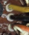
Okay, I think I can disregard the black ground wire?

I say this because when checking on the voltage on the large pwr supply cap behind the meter, and placing the negative probe on the negative of the cap and the positive probe on the chassie, I get -694. So I suppose -691 on that black ground wire is probably normal?

I actually got the idea or thought for checking the cap from something Nomadradio had said earlier on.

So I still do not know where to go from here?

RF Ktazy
 
Just a quick note, that aluminum wall plate around the mobo is at chassis ground, not board ground, and isn't useful for measuring against when working on the board. The metal "cans", transformer body and or crystal are all at board grounds, usually.
Do you have a chassis ground or board ground going to the mic? Sounds like chassis gnd to me. Check continuity between board ground and the mic ground, should be low, like an ohm or less, and no voltage difference between them. If getting -691 or whatever, could be grounded to chassis instead of board, would have to fix it.
Some pics would be great...
 
  • Like
Reactions: unit_399
Just a quick note, that aluminum wall plate around the mobo is at chassis ground, not board ground, and isn't useful for measuring against when working on the board. The metal "cans", transformer body and or crystal are all at board grounds, usually.
Do you have a chassis ground or board ground going to the mic? Sounds like chassis gnd to me. Check continuity between board ground and the mic ground, should be low, like an ohm or less, and no voltage difference between them. If getting -691 or whatever, could be grounded to chassis instead of board, would have to fix it.
Some pics would be great...
Well the ohm meter is showing 10 meg ohms between pin 1 mic ground and chassie ground when powered on. With the power turned off, the meter doesn't show any ohms at all.

It seems to me there is something shorted to ground along the mic circuit bringing the audio down.

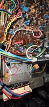
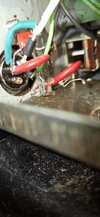
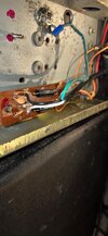
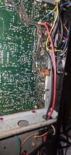
I am not sure what pics to upload, so I uploaded a few!

The power cord pic is a pic of the new cord I had replaced. The ground wire on the old flat cord was burnt and not really connected.

Although the radio had worked fine before having this issue. This burnt ground wire had been like that when I had gotten it. I had been talking on it before any of this stuff that has been going on, so its not related.

At the mic connector I have no direct chassie ground to mic ground except through the .01 caps in which I thought they block any dc anyway?

Thank you Cable Guy. If you would like any particular pic, please let me know and I will certainly upload it. I appreciate you for your help.

RF Krazy
 

Attachments

  • echo board wires.jpeg
    echo board wires.jpeg
    128 KB · Views: 5
  • Mic Jack.jpeg
    Mic Jack.jpeg
    81.7 KB · Views: 5
  • pwr cord.jpeg
    pwr cord.jpeg
    90.3 KB · Views: 5
  • main board.jpeg
    main board.jpeg
    146.2 KB · Views: 5
Last edited:
Hi RF Krazy, I finished the truck, gotta take it in for an alignment at 8:30. I got the toe in/out set pretty close just eyeballing it, but the camber/caster adjustment is beyond me so I just set it like it was. Drives like a new truck again, even without an alignment. Alright, enough shop talk. When I get back, I will look over the schematic and give you some points to check.
So, from what I gather, when you soldered the connections wrong, you just tied the mic audio input to ground, right?
Do you think you may have applied echo board power to mic input when jumpering?
Gotta figure out what was fed to the mic input.
Say, do you have a scope?
 

dxChat
Help Users
  • No one is chatting at the moment.
  • @ Crawdad:
    One of the few times my tiny station gets heard on 6m!:D
  • @ Galanary:
    anyone out here familiar with the Icom IC-7300 mods
  • @ Crawdad:
    7300 very nice radio, what's to hack?
  • @ kopcicle:
    The mobile version of this site just pisses me off
  • @ unit_399:
    better to be pissed off than pissed on.
    +1