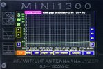
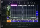
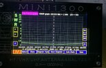
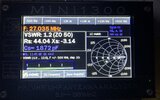
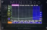
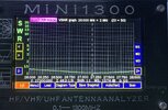
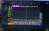
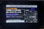
That is not a simple question and there is no single answer. There are so many factors that come into play with RF, from parasitics and ground loops to resistive losses and pattern distortion pushing current into materials they don't belong. What career PCB designers struggle with on a hand-sized scale using complex modeling software like HFSS, you are doing on a vehicle-wide scale with simple test equipment and no modeling whatsoever. There will be unanswered questions.Any idea why I could lowered the SWR to 1.0 with the radial compared with 1.3 with the rear gate opened? What’s involved here ?
This is why I would like to see you settle for a configuration that is not only permanent, but one that offers a predictably useful pattern. What you are doing (playing with that tailgate and that ground rod that is poorly attached) is just slowing you down from achieving something that you will be happy with long term. It's up to you what you want to do, but if you want my advice... Shut the tailgate, get rid of the ridiculous counterpoise rod, and get the antenna matched. Be done with it.
Edit: Or, to keep it simple, measure the swr (with the antenna and vehicle as you want to use it), calculate the voltage on the coax with that swr to ensure there will be no (literal) fire in the wire with that gigawatt amplifier (you're probably ok skipping that step), then install a tuner at the radio end to keep the radio happy with said mismatch (oh crap, did I just trigger the "tuner theory" people????)
Last edited:


