• You can now help support WorldwideDX when you shop on Amazon at no additional cost to you! Simply follow this Shop on Amazon link first and a portion of any purchase is sent to WorldwideDX to help with site costs.
  • Click here to find out how to win free radios from Retevis!

142 GTL (PC-385 Chassis) extend clarifier range?

Hawkeye351

Well-Known Member
Jun 27, 2021
569
477
73
57
Got a Cobra 142 GTL base on the desk today.


Issue(s):

1. Squeals through speaker when Transmitting.

2. Clarifier not centered at 12 o'clock.

3. Receive weak in all modes.

4. Both sidebands sound terrible.

Evaluation:

1. The external speaker jack on the back of the radio is loose, which causes a squeal through speaker when Transmitting. Fixed by tightening up external speaker/PA speaker screws.

2. PLL offset oscillators and the carrier offset oscillators are way off. Clarifier has been unlocked (not the right way though) and a 4.7uh choke tied off to the varacator diode. Also, they didn't complete the unlock procedure fully. They never removed the ground wire from clarifier to small board with switches on it. And they had the 2 wires backwards. Fixed by putting clarifier back stock, aligning all oscillators, then unlocking clarifier my way without the choke, then centered oscillators for 12 o'clock clarifier position.

3. Receive is weak due to oscillators being out of whack and the receive IF cans have been messed with. Fixed by alignment.

4. SSB sounded garbled and oscope pattern didn't look right. Fixed by replacing TR32 that someone yanked out.

Output before:

Variable on back of radio, goes from 0 (yuk) watts up to 6 watts.

PEP swing - 14w

Peak swing - 10w

Average swing - 6w

Output after:
PEP swing - 20w

Peak swing - 14w

Average swing - 9w

Clarifier slides from 27.205 center slot down to 27.2015 and up to 27.2073.

Now I'm perfectly fine with this slide range, but the owner is gonna probably want more. Which resistor controls the slide range on these PC-385 chassis? I know R175 in the 2000's and 148's you can swap out for a different value to increase the range, not sure about the 142 though.
 

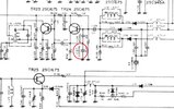
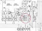
Compare the two schematics and you'll find your answer.

don't go too low with the new value though, it can be hard on the power supply when the clarifier is cranked all the way one way.

the biggest limitation to swing range you'll find is the crystal itself.
the load capacitance has a lot to do with how much you can "bend" it.
that's why the 2000's with the big crystals slide so much further than something like the grant or madison which is the same chassis but with the smaller, different crystal.

you can also try playing with different varactors.
there are many that have been tried and i can't even remember some of the names but the NTE612 used to be popular iirc.

LC
 
  • Like
Reactions: Hawkeye351
I compared the schematics of the 2000 and the 142 against each other and came up with R415, which is on the switch board and tied into where the red/white stripped wire came from factory. Someone has a jumper across this resistor. I should remove this jumper and try something like a 2k right (factory is 3.3k)?

This is the mod I used:

1. Lifted one leg of D36

2. Lifted one leg of R187

3. Removed orange and red/white stripped wires that comes from the clarifier, from their factory locations.

4. Soldered orange wire to constant +8v. I have mine tied to the positive lead of the 220v electrolytic nearest the PLL.

5. Soldered red/white stripped wire to circuit board ground on main board.

6. Realigned oscillators back to center slot on clarifier.
 
Hmmm, after thinking over it a few minutes, R415 isn't even in the clarifier circuit any more since I removed the red/white stripped wire from that location that's tied in with R415. The red/white wire is now on the main PC board ground track.

How can I get more range without that choke, with the clarifier unlocked? Like I said, I'm fine with the slide, but the owner is probably gonna want more slide than 15 lowest to 73 highest.
 
I noticed on the 2000/148 chassis, the R174 which is directly tied to the center (wiper) lead of the clarifier. Which most people place a jumper across. Well the first resistor tied in with the center (wiper) lead of the 142 clarifier is R143, which is a 10k. So, should I replace the R143 10k resistor with a 5k or a jumper to increase the range?
 
C142 Tripler Oscillator.jpg

C2000 Tripler Oscillator.jpg

The Cobra 142GTL (140GTL, Washington, et al) has C127, a 220pf cap from Emitter to Ground, where the C2000 (148, Grant XL, etc...) has a second varactor circuit from Emitter to Ground, in place of C127, this gives it the extra slide. L60 and L27 are fed from the same voltage feed from the center terminal of the Voice Lock (Clarifier). I have seen 148's and 2000's (Uniden boards) slide 20kc down (very twitchy) when opened too far.
 
I removed R143 and replaced it with a 5.1k ohm.

I now have slide from 27.2012 at the lowest position up to 27.2088 on the highest position. That's 3.8k of slide on both sides, and the clarifier is still centered at 12 o'clock for being on frequency.

I tried shorting out R143 with a jumper. The lowest would go to 27.2000 all the way down on the clarifier and the highest would go up to 27.2098 at the 3 o'clock position then it would drop off with nothing from the 3 o'clock position to all the way up.

I then decided to just replace the resistor with a lower value and it turned out great. I think 7.6k of total slide is plenty.
 
  • Like
Reactions: AudioShockwav
Should be more slide than sideband calls for. I'd say put a nail in it.

The request we tend to get is to travel down one whole channel to fill in the RC skip above 3,7,11,15 and 19.

The 148/2000 radio with the three trimmer coils works with the added choke in series with the varactor diode. This puts that choke in line with the slug-tuned coil that the mode in use selects.

The 142/Washington single-conversion radios use a trimmer cap for USB and coils only for AM and LSB. Putting the choke in series with the varactor. Makes things a bit squirrelly in many of these radios. Will "stall" the crystal and cause it to drop out at one extreme of the clarifier.

What works best for us in those radios is to cut the trace on one side of the 11.1125 crystal, and solder the choke across the cut. It does have the drawback that putting USB on frequency with the other two modes may or may not work exactly right. The USB trimmer won't quite travel far enough sometimes.

The channel center frequency will move to the right of 12 o'clock. Setting trimmer with the knob at 3 o'clock usually provides the original 1 or 1 and a half kHz above center, and added coverage below channel center. Never seems to work as well as with the 3-coil PLL circuits. This hookup behaves more consistently from one radio to the next.

Using an EXPO 100 kit made this necessary. The crystals in the kit wouldn't adjust onto frequency without the choke.

Clarifying a SSB station with a stretched clarifier gets touchy. Just touch the knob and you overshoot. Had a customer years ago who used a 142 with a 'stretched" clarifier. He drilled a hole across the clarifier knob and inserted a #4-40 screw an inch long. He could fine tune it with his thumb on the screw head better than twisting the skinny knob. A bigger knob would do the same thing, but he liked this solution.

Had to admit, it worked.

73
 
  • Like
Reactions: Hawkeye351
How bout wide banding this chassis?
Reason for asking is the low channels (below 26.765) will not lock on. I tried adjusting VCO but had no luck.

I read somewhere about removing C81 completely and replacing R84 with a 47k ohm resistor to widen it out for extra channels. Is this correct, or is there a better way other than messing around the balanced modulator IC?

The channel mod is kinda strange.
Pin 10 not cut but has a wire going to a spdt center off switch. Pin 11 track is cut with a wire on both sides of the cut going to a spdt center off switch. Then pin 12 is not cut and has a wire going to a spdt center off switch. Finally pin 17 has a wire coming off it to a spdt center off switch.

The channel mods I've seen calls for pin 10 to be cut, pin 11 not to be cut, and pin 12 to be cut.
 
Pin 10 adds 64 to the divisor when it is left open. An internal pullup resistor makes that pin a logic high (1) unless you ground it. Forcing pin 10 to zero now adds 128 to the lower divisor bits.

A radio built with the 11.325 crystal has pin 10 floating, logic 1. This is why grounding pin 10 bumps the frequency up 64 channels.

Likewise, in a radio with the 11.1125 crystal, cutting pin 10 loose from ground moves the radio down 64 channels.

Make sure L18 is peaked for max signal on TP10. Or if it's too new to have test points, probe pin 17 of the 8719 chip for peak signal.

This can affect the PLL's lock-in band width.

73
 
  • Like
Reactions: Hawkeye351
I got in contact with the owner yesterday and described how the channel mod was done and how it's acting screwy. Well, he told me that's one thing he wanted me to straighten out anyway because it was confusing to work without a frequency counter and it would drop out on a lot of extras.

I told him I'd make it simple by using the same two switches, but rewiring the PLL and switches. I told him this would make it easier for him because I would also provide a frequency map so he'll know where he's going and where he's at.

I'll give an update tomorrow on the progress.
 
  • Like
Reactions: slingslingbinks

dxChat
Help Users
  • No one is chatting at the moment.