• You can now help support WorldwideDX when you shop on Amazon at no additional cost to you! Simply follow this Shop on Amazon link first and a portion of any purchase is sent to WorldwideDX to help with site costs.
  • Click here to find out how to win free radios from Retevis!

148gtl NW ST Soundtracker low AM power

Does the back side of the heat sync get hot also, or just the transistor?

Can you measure the supply current when you DK in AM just to see if there is an unusual amount of draw?
 
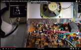
I am looking at a video that compares three different 148GTLs (not night watch) and they have one made in China that looks a lot like yours. They did use a bunch of red glue like yours and blue trimmers, so that's apparently factory glue.

That radio had a round DIM-NOR-BRT rotary switch where your dimmer knob is. Probably a difference between the regular and NW they made. There is a comment on that video about the Chinese version having poor voltage regulators too.

I'm at work and work is slow, so I will brainstorm this for a bit to try to figure out why your TIP41 is getting hot. One thing that is jumping out at me is that, in the first picture of the inside you shared, it appears that the heat sync for the AM regulator is just a small piece that is screwed to the rest of the heat sync rather than a solid piece of aluminum that wraps around the whole radio like other 148s.

I wonder if adding a little heat compound to those joints would make a difference. That frame appears to be partly steel, the other 148's use aluminum, so thats probably the source of your problem right there
 
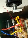
AM regulator to the side of the chassis.
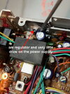
am regulator and very little draw on the power supply it has an amp meter and barely moves. the tranny and heatsink both get hot, of course the tranny get much hotter.am reg_IMG_8981.jpg
 
With the transistor getting much hotter than the heat sync, it suggests poor thermal transfer. It appears to be in good contact with the heat sync, but in this picture, my fears are confirmed that it is bolted to steel rather than aluminum, which would explain the poor transfer.

I believe the steel was yet another cost-saving measure by the Chinese. It would seem you have two options; run it as is knowing it will get hot and stressed (meaning don't sit on the mic long) or try to replace that piece of steel with aluminum.
 
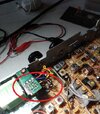
Ya know, another option would be to extend those wires and bolt that bugger on the back where there is already aluminum. The video I mentioned comparing the three 148's, I saw that someone had done that very thing to the Chinese one! Just move the AM regulator over to the aluminum.
 
  • Like
Reactions: NZ8N
The original regulator was all plastic and did not need any insulators.
With the tip41mit has the metal back so I have to add the mica insulators and used plenty of thermal grease. Yes I can give that a try im going back down to the radio and see if it steel or aluminum its mounted to.
 
  • Like
Reactions: brandon7861
Yea, it is definitely steel there. I'm betting if you move it over like in that snapshot, you'll be all set. Even with plenty of thermal paste, steel isn't good enough at conducting heat away.

I'm 99.9999% sure that was the reason the old regulator failed and your new one is getting hot. You are one step away from closing the hood and cracking open a cold one!
 
  • Like
Reactions: NZ8N
Brandon yes you are correct its steel. I will move it over tomorrow to the back like in the picture you posted. I will update later tomorrow and thanks for all your help.
 
  • Like
Reactions: brandon7861
When you do, try to route your wires a little further from the RF jack. Keep the regulator between the finals and RF jack and route the wires as close to the top of the heat sync as you can. You don't want those wires laying on the RF output lead.

edit: you may want to drill a couple extra holes for wire ties, just don't lose the drill chips. You don't want those floating around in the radio!!
 
  • Like
Reactions: Brother DXer
.


been reading this post. I have my China made 148 here that had
a few things done to it before it was given to me.
It works great now. Looks like this same main board
as you are working on. So, I just took the covers off to do
some comparisons.

looks like, by the different soldering, the RF output stage transistors
were replaced. Final TR36 is a 2SC2312 and driver TR38 is a 2SC2166.

the modulator/regulator transistor TR41 has been moved
to the back and is now a TIP3055.
.
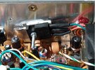
modulator TIP3055.jpg
.

in AM mode, dead key, I have 3.7 watts RF output.
power supply at 13.8 VDC input and 1.7 A of current.
5.2 VDC going to the collectors of TR36 and TR38
measured at them big blue inductors L39 and L42
at the side to the front panel of the radio.

(not a current hog like them RCI/Galaxy radios with the
IRF520's for the RF output!!) (3.5 to 4 amps!!)

I can key up, whistle, make noise, modulate it
for a long time. no problems. some heat at the
back panel at the TIP3055.


.
 
Last edited:
made in China radio?

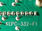
the only number I have on this board is:
.
China board number.jpg
.

and the schematic -----
 

Attachments

  • Cobra 148GTL D China schematic ver F.pdf
    433 KB · Views: 5
and one more thing.. if the same China board.

since you are already inside soldering on this board.
another known failure point, from what I have read,
and this happened to this radio I now own.
Resistor R130 to the PLL IC. it needs to be changed to a
bigger wattage, a half watt is good.
look for this blue wire.
it goes down to the board and R130 is taped up, and is
very small and may fail. replace it.

My radio here in SSB mode, it was all warbling around
in frequency. I just used it on AM.
then one day, no channel change.
PLL circuit went out. it was stuck someplace in frequency
below channel 1.

found this info out about R130 going bad, and here on this radio
R130 was way high in resistance, so soldered in a one watt 10 ohm
replacement.
.

blue wire.jpg
.

new 10 ohm resistor.jpg
 
Brandon7861.

I did the mod as you pictured and the heat is much better i dont talk long mic keys so I think it will be fine. Again thanks for your help.

BayouRadioAmplifier

Thanks for your post also with the pictures and info you provided. I think the schematic you posted is close but still not exact. As the one you posted has the 3 way sw for the dim/bright.
The radio I have has a variable in front.

I still feel something is not good in the radio.
Can you do a simple test for me.
On the mic front jack of your radio.
Can you test with a volt meter ground to pin 1 and positive to pin 3 most radio I see have 8volts and when keyed is potential ground.

This radio on pins 1 and 3 have 1.4 volts and nothing when keyed just wondering if something is killing the potential 8volts in receive on pin 3.

the receive is great just thinking why this radio is different. I have a 2000 and the keying pin has 8 v and cobra 29s have 8 volts and my galaxy 959 has 8v but not this radio.

thanks
 

dxChat
Help Users
  • No one is chatting at the moment.