My 10-80 grid-driven 4cx300a x2 amp is proceeding. I had to order parts for input. Last I reported, I had almost 100w AM from an old CB using W8Ji’s Resistive Input circuit that splits the 50 ohm swamping resistance. It was first application of drive so I used old tubes I got for free so I was happy for the moment. The G3SEK tetrode boards work properly except I cannot adjust the ALC Out. I’ll deal with that after I settle on an Input circuit.
For me, the appeal of Tetrode amp was low drive for grid-driven. That’s why I’m trying to improve upon the input circuit because it presumes 100w drive. The input impedance formula to re-determine swamping and drive values is ‘over my head’. Imaginary values are hard for me to understand and math is my weak point. I can copy OK. Pride’s parallel input is too large and the parts hard to replicate.
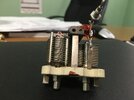
So, I found a grid driven 813 10-80 amp diagram that placed a T-50 red core (11T 20ga) across 2 Variable caps preceding a swamped input so I’m trying to copy that. I settled on a 110 ohm swamping value from a 2 x 4x250b diagram from another 10-80 amp from 1960's ARRL Handbook. The article stated that the 110 ohm value was calculated for 30w max drive. Major presumption here being that the 4x250b is same as 4cx250b/4cx300a. Guess we’ll see but it should be Ballpark and I can always go back to 50 ohm. I may need to rewind the T-50 red core for 1:2 given the 110 ohm resistance.
After looking at many Swamped input diagrams, i saw that some circuits rely on full DC grounds for the resistors while others only use RF ground via capacitors.
Is there any advantage to using one or the other grounding methods?
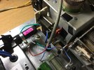
I’m almost ready to apply RF thru new input circuit. I need to reset the Screen current trip level on the G3SEK boards. It’s a day long pia but I had to relocate the 50w adjustable screen current resistor to make room for tuned input. I also re-arranged the swamp resistor section (in airbox) I can change resistors after I get all my voltages in place.
Neil
n2eye, NYC

Last edited:


