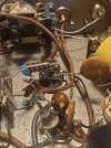
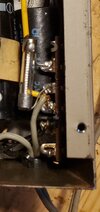
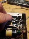
Hi all, I have a JB12 that has started red plating the 6bq5 tube and I can't seem to figure out why, I have tried replacing the coupling capacitor and have checked the values on the resistors and all seems good  does anybody have any other ideas? Thanks
You are using an out of date browser. It may not display this or other websites correctly.
You should upgrade or use an alternative browser.
You should upgrade or use an alternative browser.
-
You can now help support WorldwideDX when you shop on Amazon at no additional cost to you! Simply follow this Shop on Amazon link first and a portion of any purchase is sent to WorldwideDX to help with site costs.
6BQ5 red plating in a JB12 ?
- Thread starter Danzik
- Start date
Ah, "red plating"?
Seems to me the old folks called this "cherrying" the tube's anode, because of the shade of red you see. The anode of this type tube should never get hot enough to see any color at all. It's not built for those temperatures.
What this tells you is that the tube is drawing way more current than the safe limit. The JB12 uses a series pair of zener diodes to regulate the negative bias voltage on the control grid of the tube. That negative voltage serves to control the tube's current. They're at the very rear-most end of the tie strip where the fuse is soldered.
And your zener diodes are shorted, removing that negative voltage from the tube's grid. Makes the tube current shoot way up. Seems to me the two zeners would add up to about 30 or 35 Volts. A single 1-Watt zener will overheat and fail. Splitting the load between two of them in series makes them last longer. And a single 5-Watt zener is probably better yet.
A failed tube will sometimes shoot a surge into those zeners and croak them this way. The JB12 contains no protective circuit elements of any kind other than the line-cord fuse.
A tube that "cherries" too many times will become weak. Or it may break down and shoot a surge into the grid circuit. And the zeners.
The JB12 is a bit like a drag racer. When everything is perfect you go straight down the track. And if anything is not quite right you bounce off the wall. Could be this JB needs a tube, zeners and who knows what else. And if nobody has cleaned the relay contact points in the last 30 years, it's probably time to do that, too.
Most likely it's over 40 years old. The odds of "just one" thing alone being wrong in an amplifier that old are kinda small.
73
Great read Nomadradio! I have been looking at and testing the diodes but with them in the circuit and couldn't find a shorted or bad one but the diodes I was mostly looking at were the ones tied into the large caps, there are probably 10 of them or so, I only saw one on that rear rail by the fuse and had un soldered it and tested it and it tested out fine Ah, "red plating"?
Seems to me the old folks called this "cherrying" the tube's anode, because of the shade of red you see. The anode of this type tube should never get hot enough to see any color at all. It's not built for those temperatures.
What this tells you is that the tube is drawing way more current than the safe limit. The JB12 uses a series pair of zener diodes to regulate the negative bias voltage on the control grid of the tube. That negative voltage serves to control the tube's current. They're at the very rear-most end of the tie strip where the fuse is soldered.
And your zener diodes are shorted, removing that negative voltage from the tube's grid. Makes the tube current shoot way up. Seems to me the two zeners would add up to about 30 or 35 Volts. A single 1-Watt zener will overheat and fail. Splitting the load between two of them in series makes them last longer. And a single 5-Watt zener is probably better yet.
A failed tube will sometimes shoot a surge into those zeners and croak them this way. The JB12 contains no protective circuit elements of any kind other than the line-cord fuse.
A tube that "cherries" too many times will become weak. Or it may break down and shoot a surge into the grid circuit. And the zeners.
The JB12 is a bit like a drag racer. When everything is perfect you go straight down the track. And if anything is not quite right you bounce off the wall. Could be this JB needs a tube, zeners and who knows what else. And if nobody has cleaned the relay contact points in the last 30 years, it's probably time to do that, too.
Most likely it's over 40 years old. The odds of "just one" thing alone being wrong in an amplifier that old are kinda small.
73
Just looked at the first picture again, noticed the relay has only two circuits. A third one in the middle is usually used to shut down the tube in most versions I have seen. Makes me wonder if the filter capacitor for the negative bias voltage has quit. The zener diodes are seen pretty much only in the versions with a three-circuit relay. Not sure how they set this one up with a relay having only two circuits.
The filter cap alongside the fuse in the second picture is a possible culprit. Would be good to know what the DC voltage is on the RF choke feeding into the variable-input coil. A bum filter cap will reduce it, possibly enough to cause this kind of headache.
73
The filter cap alongside the fuse in the second picture is a possible culprit. Would be good to know what the DC voltage is on the RF choke feeding into the variable-input coil. A bum filter cap will reduce it, possibly enough to cause this kind of headache.
73
Last edited:
yes, the guy down the road brought me a JB-12
"Receive Boost Amplifier" (cute, ha ha) to repair a few months ago.
as Nomad said, the negative bias. pull that 6BQ5 out,
don't let it get red. no need for it to be in the circuit at this
point. power up and measure around negative 45
volts at tube socket pin 2, the control grid. if it's not there,
go back to the power supply and check. trace it through the circuit.
maybe the relay contact. ?? diodes, filter cap, that adjustable coil.
But sounds like your plate and screen voltages are good, if it's
getting red hot.
the JB-12 I had was worked on by someone, and they messed it up.
incorrect wiring, bad soldering. . and of course "R" and "T" are
interchanged in real life, since it is not a "Receive Boost Amplifier"
OK, thanks, AudioShock. I got the first unit, got the diagram on
CB Tricks. I told the guy that gave it to me that it says
it is a "Receive Boost Amplifier" and he said no, that they
are a TX AMP. a "little modulator" so I took another look
at the diagram, and figured it out quicky, and I laughed.
CB Tricks. I told the guy that gave it to me that it says
it is a "Receive Boost Amplifier" and he said no, that they
are a TX AMP. a "little modulator" so I took another look
at the diagram, and figured it out quicky, and I laughed.
and yes, the 2 watt resistor needed at the input
circuit if a few watts of input power, if it is a
RF power amp. that was a big hint.
circuit if a few watts of input power, if it is a
RF power amp. that was a big hint.
Hi, I have been using the JB12 as a driver and I had been having a issue with a relay within my components somewhere as it seemed I would have to key and flick the mic somtimes to get all the RX to come back in as the rx sounded faint ! However since the keying relay in this JB12 only has 2 contacts instead of 3 like Nomadradio had said, the relay wouldn't change the bias just because it is not making good enough contact in RX mode would it ????? Also, I am going to take some time today and measure some voltages for you guys to see if we can't come up with some possibilities, I am no pro at this so please Baer with me thank you for the help and adviceyes, the guy down the road brought me a JB-12
"Receive Boost Amplifier" (cute, ha ha) to repair a few months ago.
as Nomad said, the negative bias. pull that 6BQ5 out,
don't let it get red. no need for it to be in the circuit at this
point. power up and measure around negative 45
volts at tube socket pin 2, the control grid. if it's not there,
go back to the power supply and check. trace it through the circuit.
maybe the relay contact. ?? diodes, filter cap, that adjustable coil.
But sounds like your plate and screen voltages are good, if it's
getting red hot.
the JB-12 I had was worked on by someone, and they messed it up.
incorrect wiring, bad soldering. . and of course "R" and "T" are
interchanged in real life, since it is not a "Receive Boost Amplifier"
yes, the guy down the road brought me a JB-12
"Receive Boost Amplifier" (cute, ha ha) to repair a few months ago.
as Nomad said, the negative bias. pull that 6BQ5 out,
don't let it get red. no need for it to be in the circuit at this
point. power up and measure around negative 45
volts at tube socket pin 2, the control grid. if it's not there,
go back to the power supply and check. trace it through the circuit.
maybe the relay contact. ?? diodes, filter cap, that adjustable coil.
But sounds like your plate and screen voltages are good, if it's
getting red hot.
the JB-12 I had was worked on by someone, and they messed it up.
incorrect wiring, bad soldering. . and of course "R" and "T" are
interchanged in real life, since it is not a
I am only getting 17.75 -vdc at Pin 2 , 606 VDC at Pin 9 and 609 VDC on Pin 7yes, the guy down the road brought me a JB-12
"Receive Boost Amplifier" (cute, ha ha) to repair a few months ago.
as Nomad said, the negative bias. pull that 6BQ5 out,
don't let it get red. no need for it to be in the circuit at this
point. power up and measure around negative 45
volts at tube socket pin 2, the control grid. if it's not there,
go back to the power supply and check. trace it through the circuit.
maybe the relay contact. ?? diodes, filter cap, that adjustable coil.
But sounds like your plate and screen voltages are good, if it's
getting red hot.
the JB-12 I had was worked on by someone, and they messed it up.
incorrect wiring, bad soldering. . and of course "R" and "T" are
interchanged in real life, since it is not a "Receive Boost Amplifier"
I see what looks like a wiring hazard, with the yellow wire looking as if the bare part could touch one end of the soldered-in fuse. This would be a bad idea.
In the shadow under your finger there should be a filter capacitor tucked under the tie strip lugs. Its positive end will be soldered to a ground lug, and the negative end to the lug where the diode's UNbanded end is soldered. If that capacitor fails, the bias voltage will fall basically in half, more or less. None of the electrolytic caps we can see in the pic appear to have been upgraded since this unit was built 40-plus years ago. That kind of component is not meant to last even half that long. Sometimes they do, and break down in a more-exciting way after you put them back into service after years of sitting on a shelf. Changing them all, or "re-capping" as they call it is the only sensible strategy if you want to use the amplifier.
Your description of the relay problem hinges on one clue. When you unkey the mike and lose your receive, does the relay go "click" when released? Or does it just stay silently keyed up after you unkey the radio?
If you hear it go "click" every time you release the mike, cleaning the contact points with a paper strip soaked in solvent may fix the fault. And if the relay is staying activated, and won't go "click" when you release the mike you could try changing the 6AQ5 tube to see if that makes the relay release properly.
73
dxChat
- No one is chatting at the moment.


