
so i have done this on radios in the past with a TIP120, and i got some wicked clean swing from it from when i tried this 12 years ago. I have ordered some bigger darlingtons, gonna give it a whirl again because only a few chassis do the TIP120 variable DK gracefully. this is a little more complicated and permanent, requiring a trace cut upstream from the modulation transformer. and the darlington does handle a bit of current so it will need to be bolted to something to dissipate any heat from the driver/final draw through it. anyone else do something like this to drop that DK?

You are using an out of date browser. It may not display this or other websites correctly.
You should upgrade or use an alternative browser.
You should upgrade or use an alternative browser.
-
You can now help support WorldwideDX when you shop on Amazon at no additional cost to you! Simply follow this Shop on Amazon link first and a portion of any purchase is sent to WorldwideDX to help with site costs.
a swing mod (more involved)
- Thread starter Uncle Ronnie 336
- Start date

Very cool! We have never used a voltage-doubler in a carrier control, but we found that controlling the modulated power to both final and driver would slightly reduce the peak power. The problem is that a transistor will always drop a Volt or so from the circuit. The peak DC voltage on voice peaks will be a Volt and a half or so lower than it was stock. This reduces the peak power the final can muster. Not so different from the Uniden/Cobra 40-channel SSB radios. They used a NPN transistor in a Darlington pair both to modulate the DC power and control the carrier. Users would notice that the modulated peak power was always a bit less on AM than sideband. Naturally the AM-modulator transistor is not in line with the driver/final's collector power in sideband mode, putting an additional Volt and a fraction onto their collector circuits in sideband modes. Not enough difference to spit on. Just enough to see on a wattmeter. But people want what they want no matter how useless it may be. The fix is to modulate the radio's final directly and control only the driver's collector voltage. Sounds just as good. Reduces the heat-sink requirements for the carrier-control transistor in a big way.
Also found that powering the clockwise lug of the carrier-control pot from the cathode of D9 would goose it to swing the same at any carrier setting. Since our whole setup is downstream from D9 it needs an electrolytic cap in parallel with it so the audio peaks have a low-impedance path to the driver's collector.
Always more than one way to skin a cat. Found I preferred the simpler approach.
Way cool!
73
A sziklai pair. Its similar to the darlington but uses an npn amd a pnp and has only one Vbe drop.A what?
73

Sziklai pair - Wikipedia
Edit: I keep thinking it would be useful here but maybe I am not thinking about it right.
Last edited:
its been about 10 years since i tried this, and i used a tip120 for the envelope expander so i decided to upgrade that to a to-247 type for this go-round. what i want is a nice clean waveform on the scope and a 1/2 watt dkVery cool! We have never used a voltage-doubler in a carrier control, but we found that controlling the modulated power to both final and driver would slightly reduce the peak power. The problem is that a transistor will always drop a Volt or so from the circuit. The peak DC voltage on voice peaks will be a Volt and a half or so lower than it was stock. This reduces the peak power the final can muster. Not so different from the Uniden/Cobra 40-channel SSB radios. They used a NPN transistor in a Darlington pair both to modulate the DC power and control the carrier. Users would notice that the modulated peak power was always a bit less on AM than sideband. Naturally the AM-modulator transistor is not in line with the driver/final's collector power in sideband mode, putting an additional Volt and a fraction onto their collector circuits in sideband modes. Not enough difference to spit on. Just enough to see on a wattmeter. But people want what they want no matter how useless it may be. The fix is to modulate the radio's final directly and control only the driver's collector voltage. Sounds just as good. Reduces the heat-sink requirements for the carrier-control transistor in a big way.
Also found that powering the clockwise lug of the carrier-control pot from the cathode of D9 would goose it to swing the same at any carrier setting. Since our whole setup is downstream from D9 it needs an electrolytic cap in parallel with it so the audio peaks have a low-impedance path to the driver's collector.
Always more than one way to skin a cat. Found I preferred the simpler approach.
Way cool!
73

Ronnie i've never actually built it.
I just happened to be part of the discussion back when That one guy brought it to the group without part values.
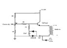
looks like i may have gotten the pot value wrong, as you say the one you built did indeed work well.
did you find you had to add that 470uF cap i have drawn in mine?
i believe that's for receive audio, but i drew that so long ago i can't remember lol.
thanks for bringing this idea a new life!
i do hope people try it and post results.
LC
I just happened to be part of the discussion back when That one guy brought it to the group without part values.
looks like i may have gotten the pot value wrong, as you say the one you built did indeed work well.
did you find you had to add that 470uF cap i have drawn in mine?
i believe that's for receive audio, but i drew that so long ago i can't remember lol.
thanks for bringing this idea a new life!
i do hope people try it and post results.
LC
if i remember correctly i was a part of that thread initially and ummm, cbtricks forum? i remember the guy was a pretty high-level tech, forget his handle.
so theres a pc66xl with an rfx75 and a couple of uniden 510's kickin around with this in it that i did up. the 66 had a hi-lo swith on the ch9 switch, and it would key 2 and swing 80 with no distortion at all on low
so theres a pc66xl with an rfx75 and a couple of uniden 510's kickin around with this in it that i did up. the 66 had a hi-lo swith on the ch9 switch, and it would key 2 and swing 80 with no distortion at all on low
well ive got to try it next time i get a 29 or other AM transformer modulated radio through here.
LC
LC
yea, i might just exclusively with this method. pulling the driver jumper and doing the NPC that way even on a 29 leaves a flatline across the middle of the scope, even with the limiter set to clip. its only less-worse on them models than other chassis rigs that i've tried that with for some reason
dxChat
- No one is chatting at the moment.
-
-
-
-
@ kingmudduck:Hello to all I have a cobra 138xlr, Looking for the number display for it. try a 4233 and it did not work
-