
You are using an out of date browser. It may not display this or other websites correctly.
You should upgrade or use an alternative browser.
You should upgrade or use an alternative browser.
-
You can now help support WorldwideDX when you shop on Amazon at no additional cost to you! Simply follow this Shop on Amazon link first and a portion of any purchase is sent to WorldwideDX to help with site costs.

a swing mod (more involved)
- Thread starter Uncle Ronnie 336
- Start date
if you can post those, i would love that. im gonna try to get ahold of one of my friends who has the 66xl. I would like to see the horrors of my work 10-12 years agoI may have saved Laz's postings on his Controlled Carrier circuit. I'll look when I get home
I saved 11 pages and I don’t know how to post them here . Lazarus posted a few different radio adaptations ie Galaxy, President Jackson and the modulation transformer type radios. Nomad and LC were active in that thread. Here’s a snippet from page 11 from Laz:if you can post those, i would love that. im gonna try to get ahold of one of my friends who has the 66xl. I would like to see the horrors of my work 10-12 years ago
I'm gonna give a condensed description of the circuit in the OP, in an effort to prevent having to repeat it over and over again in private messages,
OK, here goes, How It Works,
The Darlington pair Q1 and Q2 are simply acting as a pass transistor,
R1, R2, and R4, make up a variable voltage divider which sets the idle bias of the Darlington pair, thus controlling the unmodulated carrier level,
R1 sets the maximum level at which R2 can adjust the idle bias level of the Darlington pair, therefore lowering the value of R1 will increase the maximum idle bias level, R4 sets the minimum level at which R2 can adjust the idle bias level of the Darlington pair, therefore lowering the value of R4 will decrease the minimum idle bias level, D1. D2, C1, and C2, make up a circuit known as an envelope detector,
C2 allows a small sample of the high level audio signal to pass through it to D1 and D2, where it is rectified, C1 then filters this rectified audio signal into a smooth DC voltage which proportionally follows the audio signals amplitude or envelope,
This smoothed out DC representation of the audio envelope is then fed to the base of the Darlington pair where it upsets the idle bias level set by R2, thus causing the carrier to rise in proportion to the audio envelope, therefore the louder you speak into the microphone the higher the carrier will rise as a result, and the value of C1 will determine how fast the carrier decays after modulation stops, for a slower decay time, increase the value of C1, the function of R3 and R5 is simply to allow each of the controlling circuits (the voltage divider and the envelope detector) to work independently without effecting each other, in other words, the envelope detector needs to be free to raise the bias on the Darlington pair without being loaded down by the setting of R2, without the use of R3 and RS that wouldn't be possible,
With a little effort tinkering with component values one can easily have this thing achieving a 100% modulation envelope at all times,
ideally the average DC output voltage of the Darlington pair into the modulator winding of the audio transformer, should be half that of the peak to peak voltage measured across the modulator winding at any given time during modulation, in which case the modulation envelope will be maintained at or near 100% at all audio levels,
OK, i think that pretty much covers everything
Last edited:

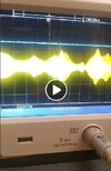
IT WORKS FLAWLESSLY
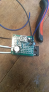
1st prototype using the TIP142 has me swinging wicked clean on a president zachary T. we're talkin .4w swingin 15PEP. i'm happy. so there you have it. 2.2uf delay, TIP142 for a bigger regulator, and i believe this things ready for bigger-final rigs
1st prototype using the TIP142 has me swinging wicked clean on a president zachary T. we're talkin .4w swingin 15PEP. i'm happy. so there you have it. 2.2uf delay, TIP142 for a bigger regulator, and i believe this things ready for bigger-final rigs
Thanks for that 711!
I might have that thread saved somewhere but i'll never find it.
I was a bit surprised by Nomad's response to Ronnie's post because i remember him being in the original thread.
Did anyone ever try this with a radio that also had an RFX unit on the back?
that could be interesting!
LC
I might have that thread saved somewhere but i'll never find it.
I was a bit surprised by Nomad's response to Ronnie's post because i remember him being in the original thread.
Did anyone ever try this with a radio that also had an RFX unit on the back?
that could be interesting!
LC
From Lazarus pg 8
for those of you who may be trying to implement a 29-LTD or similar chassis with this circuit, i thought i would share a little problem i ran into when i did mine, and the solution to it,
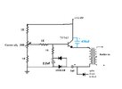
because of the way the the 29 and similar type chassis are modulated through the primary winding of T1 instead of the secondary like real radios are, i had to place a 25v 470μf electrolytic cap across the emitter & collector of the Darlington pair, in order to restore the receive audio that was lost, due to the loss of inductive coupling through T1 when it was isolated from the B+ supply,
the only other solution to this problem would be to rewind T1 with 3 separate windings, one for the primary, one for the modulator, and one for the speaker, which is how it should have been done in the first place, i don't like the way it's wound at all, the wire is too small and theres not enough turns, both of which are largely responsible for the less than desirable low end response that this chassis exhibits,
here's a pic to help illustrate how to apply this modification to this type chassis, i have edited everything out thats not related to this modification and stretched a few lines here & there for clarity:

.jpg")
for those of you who may be trying to implement a 29-LTD or similar chassis with this circuit, i thought i would share a little problem i ran into when i did mine, and the solution to it,
because of the way the the 29 and similar type chassis are modulated through the primary winding of T1 instead of the secondary like real radios are, i had to place a 25v 470μf electrolytic cap across the emitter & collector of the Darlington pair, in order to restore the receive audio that was lost, due to the loss of inductive coupling through T1 when it was isolated from the B+ supply,
the only other solution to this problem would be to rewind T1 with 3 separate windings, one for the primary, one for the modulator, and one for the speaker, which is how it should have been done in the first place, i don't like the way it's wound at all, the wire is too small and theres not enough turns, both of which are largely responsible for the less than desirable low end response that this chassis exhibits,
here's a pic to help illustrate how to apply this modification to this type chassis, i have edited everything out thats not related to this modification and stretched a few lines here & there for clarity:
Last edited:

Froggy was active, so was Bow, Gadget, Sonoma, 2x4 and Billy to name a few. I never got around to trying it.Thanks for that 711!
I might have that thread saved somewhere but i'll never find it.
I was a bit surprised by Nomad's response to Ronnie's post because i remember him being in the original thread.
Did anyone ever try this with a radio that also had an RFX unit on the back?
that could be interesting!
LC
yeah neither did i.
i did have the note about the 470uf cap, so that must've come from you.
and thanks for all the diagrams!
LC
i did have the note about the 470uf cap, so that must've come from you.
and thanks for all the diagrams!
LC
i did 12 years or so ago. that rig screamed. 2 swingin 80 all dayThanks for that 711!
I might have that thread saved somewhere but i'll never find it.
I was a bit surprised by Nomad's response to Ronnie's post because i remember him being in the original thread.
Did anyone ever try this with a radio that also had an RFX unit on the back?
that could be interesting!
LC
you should definetly try it. this is gonna be my go-to from here on out instead of the npc/rc things with the tip120 in the driver's path. so much betterFroggy was active, so was Bow, Gadget, Sonoma, 2x4 and Billy to name a few. I never got around to trying it.
quite honestly, this thread should be pinned. the less people snip limiters and do a 2w resistor and cap, the better for the noise levels when that skip opens up. the thing is, even if you just crank the limiter open for happy watts and get a little pinching in it, it's still way less than any NPC mod in the path of the driver.
Attachments
I guess I gotta make a board to try it now. My perf boards all look like poop lol.corrected the schematic too.
