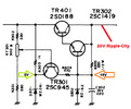
D302 is not the problem. Doing the exact same thing with the 3, 5.6v diodes in Series. But putting out 7 volts this way.
-
You can now help support WorldwideDX when you shop on Amazon at no additional cost to you! Simply follow this Shop on Amazon link first and a portion of any purchase is sent to WorldwideDX to help with site costs.
-
The Feb 2025 Radioddity Giveaway Results are In! Click Here to see who won!
Another 139XLR power supply problem.
- Thread starter Low_Boy
- Start date
Well, over 19v across a 16v zener is FOR SURE a problem. So is huge difference in base and emitter voltages you reported earlier for TR302. If you have the zener holding down to 16.something volts, then switch TR302 to one you haven't already had in there (because 10v across its BE junction is disastrous to the transistor). Then, once that is in, turn that variable resistor back and forth and see what happens. But do it in that order only. Check for 16v (it can't be 19v), then the 302, then, if adjusting that variable does not do it, get the BCE voltages again with the variable centered.
I also at one point today removed the variable resistor and cleaned and tested it. I do not want to take TR302 out too many more times if I do not have to. Someone many years ago had it out. I can tell by the age of the part but they pulled a pad and loosened another. I repaired it but want to try to keep it looking as good as possible.
If things were working correctly...

The Zener's force the voltage limits - the only variable is RT301.
So at one point, you got D301 working right but the opposite one, which should be at 16V was more like 19V - so we lost D302 - it should always have been "set" for 16 V - anything less or more, you have a problem. It can't regulate.
It is not necessary to use EXACT components unless they are package specific.
Meaning - you don't have to use a 1419 - when something NPN with a similar pinout can do the job.
JJ, Thank you I am going to make a copy of that and put it in my Sam's. By memory the rectifier diode is wired correct and tomorrow I will will check the board. I only changed a couple wires I even used the correct color codes lol.
We have hours and hours and hours. Trying to get this working. So with D302 removed I figure I will put my volt meter on cathoid pad of D302 and adjust RT301 and see if the voltage changes. By the way all 3 legs of RT301 have continuity to the catholic which does not seem right? I plug the radio in turn it on without D302 and touching nothing.
The radio turns on all voltages are correct.............What just happened?
The radio turns on all voltages are correct.............What just happened?
Bun no matter how much I adjust RT301 I can not get the voltage on D302 below 23 volts and that is with RT301 all the way one way. And any where else 24V.
EDIT EDIT>> I am hoping I caught this in time. I looked at the schematic again RT301 Will adjust base voltage of R302. By my schematic the ideal voltage is 15V. I am not sure what will get the voltage on D302 down.
I also mentioned in the last post all 3 legs of RT301 were showing continuity to D302 but I must have been wrong and possibly a cap was charging. I am not getting that now. I think my new problem is getting voltage on D302 down and possibly things will work correctly. OK D302 is a voltage regulator that should bring 24V down to 16 but for some reason is not working? But without D302 in circuit the power supply works?
Sorry for rambling.
Last edited:
It is IMPERATIVE that you do not power the radio without D302 in place and functioning. Doing so is a guaranteed death to TR302 as the base-emitter voltage will be greatly exceeded (as I've already commented on a few times). You cannot expect any sort of positive result other than more damage running the radio without that 16v zener in place!!!!!
If you get tired of messing with it, you could send me just the power supply board and TR401 (not the transformer or rectifier or anything else), I will take a look, try to repair it, and send it back. We can make a video out of it for the next person that runs into this problem. There has to be something being overlooked and I'd love to get my hands on it....
Worst case scenario is I fail and we both lose $5 in shipping, but I don't think that's how it's gonna go because I'm not trying to look like an ass on this forum lol. I'll even send some thermal paste on the return trip for when you remount TR401 ~ it's not the most expensive stuff, but it will be better than nothing. Just don't lose that thin mica insulator or the screw insulators when taking it off...
If you want to take me up on that offer, PM me and I'll send you my mailing address. As soon as these muddy northern MN roads dry, I'll become very busy cutting wood, so the sooner the better if that's what you want to do.
Well I just had a brain storm. I was wondering ,,if that was working when I got it. And not working after a rebuild. Was it only working because it had a bad part. I saw in one of the pictures D301 was corroded. And it tested good. D302 was the other diode. It was blown showed continuity both ways. But that means D302 was shorting to ground.
If it was shorting to ground, that means all 25v was across that 220Ω resistor. 25/220=114mA, which at 25v would be 114mA*25v=2.84watts. That would have SMOKED that little half watt resistor 
If it were on my bench, I would remove TR401 AND TR302. This would also serve to turn off TR301. At this point, the only thing in circuit would be the 16v zener, which would be the first thing that would be fixed. Then, again with both TR401 and TR302 out, I would apply an external 13.8v to the lead that would otherwise go to the emitter of TR401. This would serve as the proper voltage for the feedback and allow me to set RT301 (assuming TR301 was working) such that TR301's collector had the necessary 15.2v on it (or whatever the junction drops from the darlington pair would establish). Then, and only then, would I replace TR302 (again, with my external supply providing the feedback voltage and TR401 still disconnected). In this state, I would ensure that TR302's emitter was at 14.5v. From there, The 25v would be disconnected, my supply of 13.8v would be removed, then TR401 would be replaced (if it tested good). IN THAT ORDER.
Before I totally say I can not do it those will be my next steps. I have been suspecting TR401 but this will tell for sure.
dxChat
- No one is chatting at the moment.
-
-
@ Geoexplorer69:Coax question. I just put up a new Sirio monsoon base antenna with 100’ of rg8u coax testing with myMFJ antenna analyzer shows 1.4 swr at 26.965mhz and a 1.1 at 27.405 mhz . When I checked the ohms it’s steady a 30 ohms across the entire bandwidth.
-
-
-


