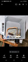
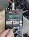
It's still 1.5What is the swr on 1, 20, and 40? It sounds like you just need to retune your antenna
You are using an out of date browser. It may not display this or other websites correctly.
You should upgrade or use an alternative browser.
You should upgrade or use an alternative browser.
-
You can now help support WorldwideDX when you shop on Amazon at no additional cost to you! Simply follow this Shop on Amazon link first and a portion of any purchase is sent to WorldwideDX to help with site costs.
Antenna Tuning
- Thread starter MadisonMod
- Start date
Is it possible that the new coax has less loss, and, due to that less loss, a larger portion of the same reflection is making it back to the SWR meter?
Going from 1.5kW to 4kW assumes a different amplifier. Perhaps a slightly different output tune?
I think that trying to get lower than 1.5 SWR is going to take verifying (or measuring) the output impedance of the amp, the (actual) characteristic impedance of the cable, and the feed point impedance of the antenna. It may not be worth it as 1.5 SWR isn't bad.
Another thing that comes to mind is the ground loop formed between the radio and antenna feed point. This is a subject that I am just starting to learn about (reading Noise Reduction Techniques in Electronic Systems by Henry Ott at work when not busy and I am currently in the chapter of magnetic shielding). Although my understanding of the material is quite limited at this time, the power increase jumps out at me as being a possible culprit. Consider the loop formed between the coax and vehicle body. At both ends of the coax, there is a connection to vehicle ground (making a loop). If the loop those two make has any area to it (the coax shield not tightly ran along the same path the RF takes through the vehicle body), it can pick up more flux, and the larger magnetic component of the near field due to the increased power might induce a larger current in the shield. I don't claim to fully understand what that book is telling me yet, but it may be an avenue of investigation. Once I absorb that book in its entirey, I may be better suited to take on these kinds of problems I hope.
Edit: just got out of shower and wanted to elaborate more on the ground loop thing. For a varying magnetic field to induce a current in a conductor, it must be a closed loop electrically. Current can't flow if it has nowhere to go. And since the center conductor isn't similarly at RF ground at the antenna side, the magnetic field induces more current on the shield than it does on the center conductor. This means the voltages induced in the cable shield and center conductor from the near field magnetic component do not cancel out (there is now a differential mode signal combining with the main signal), and the radio might see this (or it's effects) as reflected power.
Going from 1.5kW to 4kW assumes a different amplifier. Perhaps a slightly different output tune?
I think that trying to get lower than 1.5 SWR is going to take verifying (or measuring) the output impedance of the amp, the (actual) characteristic impedance of the cable, and the feed point impedance of the antenna. It may not be worth it as 1.5 SWR isn't bad.
Another thing that comes to mind is the ground loop formed between the radio and antenna feed point. This is a subject that I am just starting to learn about (reading Noise Reduction Techniques in Electronic Systems by Henry Ott at work when not busy and I am currently in the chapter of magnetic shielding). Although my understanding of the material is quite limited at this time, the power increase jumps out at me as being a possible culprit. Consider the loop formed between the coax and vehicle body. At both ends of the coax, there is a connection to vehicle ground (making a loop). If the loop those two make has any area to it (the coax shield not tightly ran along the same path the RF takes through the vehicle body), it can pick up more flux, and the larger magnetic component of the near field due to the increased power might induce a larger current in the shield. I don't claim to fully understand what that book is telling me yet, but it may be an avenue of investigation. Once I absorb that book in its entirey, I may be better suited to take on these kinds of problems
Edit: just got out of shower and wanted to elaborate more on the ground loop thing. For a varying magnetic field to induce a current in a conductor, it must be a closed loop electrically. Current can't flow if it has nowhere to go. And since the center conductor isn't similarly at RF ground at the antenna side, the magnetic field induces more current on the shield than it does on the center conductor. This means the voltages induced in the cable shield and center conductor from the near field magnetic component do not cancel out (there is now a differential mode signal combining with the main signal), and the radio might see this (or it's effects) as reflected power.
Last edited:
Thank you for your thoughts. I will research and investigate. I appreciate itIs it possible that the new coax has less loss, and, due to that less loss, a larger portion of the same reflection is making it back to the SWR meter?
Going from 1.5kW to 4kW assumes a different amplifier. Perhaps a slightly different output tune?
I think that trying to get lower than 1.5 SWR is going to take verifying (or measuring) the output impedance of the amp, the (actual) characteristic impedance of the cable, and the feed point impedance of the antenna. It may not be worth it as 1.5 SWR isn't bad.
Another thing that comes to mind is the ground loop formed between the radio and antenna feed point. This is a subject that I am just starting to learn about (reading Noise Reduction Techniques in Electronic Systems by Henry Ott at work when not busy and I am currently in the chapter of magnetic shielding). Although my understanding of the material is quite limited at this time, the power increase jumps out at me as being a possible culprit. Consider the loop formed between the coax and vehicle body. At both ends of the coax, there is a connection to vehicle ground (making a loop). If the loop those two make has any area to it (the coax shield not tightly ran along the same path the RF takes through the vehicle body), it can pick up more flux, and the larger magnetic component of the near field due to the increased power might induce a larger current in the shield. I don't claim to fully understand what that book is telling me yet, but it may be an avenue of investigation. Once I absorb that book in its entirey, I may be better suited to take on these kinds of problemsI hope.
Edit: just got out of shower and wanted to elaborate more on the ground loop thing. For a varying magnetic field to induce a current in a conductor, it must be a closed loop electrically. Current can't flow if it has nowhere to go. And since the center conductor isn't similarly at RF ground at the antenna side, the magnetic field induces more current on the shield than it does on the center conductor. This means the voltages induced in the cable shield and center conductor from the near field magnetic component do not cancel out (there is now a differential mode signal combining with the main signal), and the radio might see this (or it's effects) as reflected power.
dxChat
- No one is chatting at the moment.
-
@ kingmudduck:So I have a cobra 138xlr and the meter dose not work... It dose not key up and signal dose not work.... It is not stuck it the meter moves freely. now wires are resoldered on both ends...So now that do I look at. Could it be a diode or a transistor?
-
dxBot:Greg T has joined the room.
-
dxBot:Greg T has left the room.
-
-


