• You can now help support WorldwideDX when you shop on Amazon at no additional cost to you! Simply follow this Shop on Amazon link first and a portion of any purchase is sent to WorldwideDX to help with site costs.
  • Click here to find out how to win free radios from Retevis!

ASTROPLANE best vertical antenna ever?

Next time , I will measure everything and take pics for you to see. A friend of mine told me that the Fiber Glass spreader goes 43” from the Stainless Steel Plate. Is he correct ?

I am asking because instruction manual is very vague and the say. In other words this manual just say: “ Look at the picture # ... “ . It lacks these type of details. The manual also say that in order to have good SWR, this antenna should be away from other antennas, metal objects, etc.

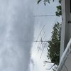
As you can see in the pictures, mine is pretty close to “ other antennas” . As you can see in the pictures, the top of the Astro Plane is close to my yagi.

I still don’t know why Avanti didn’t state how to tune this antenna.

Here are the SWR readings :

SWR. Frequency

2.0 25,895
1.5 26,365
1.0 27,205
1.5 27,805
2.0 28,105

Bandwidht: 2,210 KHz

That was with an external SWR meter. I didn’t think this antenna would be so broad banded.

Marconi, I’ll have to wait this next weekend to provide you with the info you request.

Here are some pics for you to see.

Sorry for the pics. I don’t know why the are rotated. I tried to fix it but I could not do it.
 

Attachments

  • 13E28CA7-DEBA-418E-91F2-6FEC05FFD8BF.jpeg
    13E28CA7-DEBA-418E-91F2-6FEC05FFD8BF.jpeg
    205.2 KB · Views: 10
  • CCB43E54-D977-4915-AD9F-0A4F3F1B416E.jpeg
    CCB43E54-D977-4915-AD9F-0A4F3F1B416E.jpeg
    247.2 KB · Views: 9
  • 21020786-71C4-4C65-A791-64939D70F6A6.jpeg
    21020786-71C4-4C65-A791-64939D70F6A6.jpeg
    195.8 KB · Views: 10
  • 8DE43734-2398-44E7-9960-94E5ED39586C.jpeg
    8DE43734-2398-44E7-9960-94E5ED39586C.jpeg
    131.6 KB · Views: 9
  • BEDE8EA6-0D09-4CD4-B023-9E11FFD99FC7.jpeg
    BEDE8EA6-0D09-4CD4-B023-9E11FFD99FC7.jpeg
    295.2 KB · Views: 8
  • 08B9F122-EE1C-44E3-A292-DB91F52766D5.jpeg
    08B9F122-EE1C-44E3-A292-DB91F52766D5.jpeg
    320.9 KB · Views: 9
Last edited:
  • Like
Reactions: Marconi
Marconi.

Can you give me a question list ? I’ll be taking it down this weekend . Those questions will be useful for me as well.


Some answers to the questions you made

1- I can move the radials closer or farther if I loose the clip.

2- I mounted the radial clip according with the instructions: “ Look at the picture “, just above where they meet . Can you believe it ? ( see pic)

3- The picture with the measurement is from the top to the bracket.
 

Attachments

  • 3CDDB099-3AF2-4D1D-9915-B611A55E68F8.jpeg
    3CDDB099-3AF2-4D1D-9915-B611A55E68F8.jpeg
    224.7 KB · Views: 10
  • Like
Reactions: Marconi
Next time , I will measure everything and take pics for you to see. A friend of mine told me that the Fiber Glass spreader goes 43” from the Stainless Steel Plate. Is he correct ?

Thanks Alexis, you have always been very helpful to me.

43" inches sounds a little short to me, but I asked Bob about that issue and he said he did pretty much what you did and his A/P has had no problems in maybe 5-6 years. My exposed top and bottom radials, in my typical A/P model, are 45.5" x 1/2" at the top and 45.8" x 1/2 inches at the bottom. That said my models show some positive (+) reactance at the feed point and that means some wires are a bit long. So, you might have received some good advice from your friend. Your dimensions, may make the difference I see in the match for my models. I have never owned a real A/P.


I am asking because instruction manual is very vague and the say. In other words this manual just say: “ Look at the picture # ... “ . It lacks these type of details.

I think the A/P is basically...not meant to be a tunable antenna. There are some areas that will allow one to effect the resistance and the reactance however, and that can change the match and resonance somewhat.

The manual also say that in order to have good SWR, this antenna should be away from other antennas, metal objects, etc.

That is a standard good practice rule for antennas...sometimes it is just not convenient. My space at home is limited, so I sometimes had several antenna in the air.

As you can see in the pictures, mine is pretty close to “ other antennas” . As you can see in the pictures, the top of the Astro Plane is close to my yagi.

Maybe it's not the best setup, but if being close does not appear to ill-effect the match to bad...being close is better than no antenna at all.


Marconi, I’ll have to wait this next weekend to provide you with the info you request.

That's great Alexis. I'll send you and image, in a private conversation, of the antenna showing the particular dimensions I'm looking for. Basically I'm looking for exposed lengths only, not the overall lengths like you see when opening the box for the first time and in the parts list of the Manual.
 
Last edited:
By the way, I used 9913 coax cable. I don’t recall the length but I think it’s not relevant. It is connected to a Ameritron RSC-4 remote coax switch inside the tower.
 
  • Like
Reactions: Marconi
Marconi.

Can you give me a question list ? I’ll be taking it down this weekend . Those questions will be useful for me as well.


Some answers to the questions you made

1- I can move the radials closer or farther if I loose the clip.

2- I mounted the radial clip according with the instructions: “ Look at the picture “, just above where they meet . Can you believe it ? ( see pic)

3- The picture with the measurement is from the top to the bracket.

1. That is good to know, thanks.

2. I was just being cautious. The bottom looked like the only securing support it gets looks like the small screw in the u-shaped clip Avanti used. It just looked weak for being in the wind and weather. Bob said you did good and I take his word for that...he has an new old A/P in England and he loves it, and it have been up for about 5 years with no problems.

3. That is what I thought, and it looks to be about 46" inches exposed. Others have claimed different lengths for this top shortened radiator with a Top Hat. I have my model set at 45.5" inches...so I'm a little short. Can you tell me how deep the radiator goes down into the hub bracket, and if the top radial below goes up inside the tube and the hub bracket about the same length, 2 inches more-or-less?

I sent you an images with some notes indicating the dimensions I'm looking for. Check it out in the conversation I sent you, and if it does not explain well enough...then let me know, OK?

Alexis, i really appreciate your helping me in this.
 
  • Like
Reactions: Alexis Mercado
By the way, I used 9913 coax cable. I don’t recall the length but I think it’s not relevant. It is connected to a Ameritron RSC-4 remote coax switch inside the tower.

I have one of those switch boxes, but I think I found it sometimes troublesome with some antennas I hooked up to it.

I did not understand anything about Common Model Currents back them, but now I suspect that was the issue I was likely experiencing.

I have seen guys on videos using them and they love the utility of it, in and out of the radio shack..
 
Marconi.

Can you give me a question list ? I’ll be taking it down this weekend . Those questions will be useful for me as well.

Sure Alexis.

Starting at the top, and assuming the antenna is assembled. For modeling reasons, I'm looking for exposed lengths only, in inches, and not the lengths noted in the Manual on the parts list.

1. the top hat, length and diameter.

2. the radiator, exposed length and diameter, from the top of the hub to the top hat wires. You showed us a picture of this dimensions...and I noted the radiator exposed length to be 46" inches of the tube that was 48" inches as noted in the Manual' parts list...this difference is what I mean when I talk about, exposed length.

3. the width and height of the antenna mounting bracket.

4. *** also on antenna mounting bracket hub, I need the space between the two radials, center to center, and measured at a point right below this mounting bracket hub noted in question #3.*** See note below.

5. the exposed length and diameter for the 2 top sections of the radials.

6. *** the radial to mast bracket that is between the 2, top and bottom radials is a space dimensions also that is very sensitive to the match. I need this space dimension also, as measured from center to center of the 2 radials.*** See note below.

7. the exposed length and diameter for the 2 bottom sections of the radials.

8. the diameter and/or radius of the loop at the bottom of the antenna.

Alezis, this is what I tried to describe in the crude image I sent you earlier in a conversation.

Note for this notation (***) above: it is important to be precise with these particular measurements, out to the fractions of an inch if necessary, no rounding please.

Reason is, these dimensions are very sensitive to the tuning of the antenna, and a very little change or a difference...can make a notable difference in matching results.

Alexis, any questions, just ask.
 
Last edited:
  • Like
Reactions: Alexis Mercado
The oto hub you sent me is still at the old place so i can't compare them at the moment but i will recheck the astroplane hub for you back in 5minutes.

right under the hub as close to the tube centers as I can get it with my eyes & measured with a steel engineers rule my astro measures 6-1/16"

Bob, I hope you're alright.

I did some searching and I found this old thread where you posted the radial spacing for the mounting hub for the Old Top One I sent you. Click link below.

AstroPlane up and Testing

I also found an old thread that shows the A/P mounting bracket dimensions posted by Starduster.

img_2156-jpg.2708
 
Last edited:
Yes im OK Eddie, Not much I can do in lockdown, apart from some metal detecting in local fields,
won't be long before we are in Full lockdown again if things keep going in the same direction,

IM pretty sure my astroplane measured 6" at the top of the hub,
but when I checked tube center with a more accurate engineers rule rather than a tape measure as seen above under the hub it was a shade over 6". Probably nothing to worry about,
6" is very close & my eyes aint perfect.

i just had a thought Eddie, when the bracket is loose it may measure a littel different than when everything is snugged up tight on the mast.

i would go with 6" & that will be very close.
 
Last edited:
I agree Bob, the A/P radial space is 6" inches at the hub. I think the picture above is pretty conclusive that the hub is 6" inches. And, you just measured it again at 6" inches too. So, the radial space on the A/P hub is likely just 6" inches.

IMO, something else looks to be wrong with my model however.

My goal in this model is to use the A/P dimensions, I have, and do not change those dimensions to effect the match. That is probably the way you would setup your A/P and mount it, right out of the box...expecting to see a good match somewhere in the CB band, right?

IMO so far, these dimensions or the construction used is not producing a good model with a good match as we should expect. So, I think the model dimensions are not right and/or I could have a construction issue as well...............

I just did a test on a model with a full 1/4 wave radiator, deciding to make whatever changes to the dimensions I found necessary (breaking my rule to keep the dimensions to specs.) Below is what happened.

I wanted to get the model to show a good match, report and AG result = 1 in Free Space, show good resonances in the CB band, with a improved bandwidth, over the version with a Top Hat. I also wanted to be able to use a 1.50" mast from the hub to the ground...including an insulator somewhere in the mast, like an antenna mast inside the antenna and extending below the loop some length set at 220" inches.

I used my tuning features, (again breaking my dimension rule) working with segment count, wire diameter at the two short wires at the feed point hub, and adjusting the length of the full 1/4 wave radiator to resonance. These specific adjustments do not change the A/P dimensions IMO.

Initial results show I cannot use a 1.50" mast. When I try and get the radiator to a resonant length...the model will tune toward resonance.But, when I reach a point in adjustments the changes just stops...leaving a small amount of resonance in the model.

Ordinarily, a little reactance is not a problem, but in this case...the model seems to be showing me...the feed point is not in the right location.

I could be wrong though, because the OTO model seems to work just fine with the feed point on 1 of the 2 short wires (the hub)...like DB showed me sometime back, It just made sense and it was simple idea.

The OTO works with a 1.50" mast and gives a very good match without tuning...I don't even have to fiddle with the segment lengths.

I don't have any evidence, that I can show yet, but I'm working on some ideas that will make construction changes for the hub.


Last edited:
Eddie,
i wish i could help with the how to construct the hub area in eznec, im thinking that's likely where the problem is, big changes in diameter at junctions but i am guessing.

i only remember some of what Cebik says about segment lengths & junctions in transmission-lines,
& some issue with different diameter tubes when the fat section is near the middle of the antenna not giving the right gain but it was only a small error


The vswr readings Alexis posted are almost identical to what i had with the 1/2wave 1.5" mast so we know the mk2 astroplane is tuned for the middle of your band,

The old version may have been tuned for your old channel regs.
 
I don't even know what a MK2 Astro Plane is?

I guess I missed this version. Must be something made in Europe.
 
Last edited:
The first astroplane I had years ago that I call the MK1 was old when I got it in the early 80's,

the lower legs where straight tubes that slotted into an expanded upper tube,
I am 99% sure the hoop also had expanded joints not swaged,

mk2 is the one I have now with swaged tubes, the user manuals I can find online are the mk2 version,

look at the astrobeam user manual & compare tubes with the astroplane parts list,
that shows how my original astroplane was constructed,

my first astro came off the first cber in this area so it must have been a late 60's or early 70's antenna,

at some point the design was changed to what I have now,

possibly when A/S bought Avanti & changed the sigma2 & sigma4 in the early 80's,
or when you got 40channels because the astroplane has fixed tuning,

my astroplane user manual says copyright 1978, the box is also different to the one i had years ago.

i got the lower tubes wrong but its been a long time & i did not have it long Eddie.
 
Last edited:
  • Like
Reactions: Alexis Mercado
I don't doubt you Bob, but I don't think I was aware of any of this. :LOL::LOL:

I remember you had an AP, but I didn't know you got the 1st CB antenna in your area.

I can see you now, 16 years old, climbing up a 70' scaffold pole in your Daddy's pasture, with an A/P strapped on you back, with a bag of tools, and a sack lunch...and you can't wait to get that bugger mounted.(y)(y)

How did that thing work?
 
Last edited:
  • Like
Reactions: Slowmover

dxChat
Help Users
  • No one is chatting at the moment.