I have seen so much misinformation about this topic here and elsewhere on the web, that I felt compelled to make this post. I hope AT-6666/SS 9900 owners will be able to use this information to successfully wire ANY microphone to their radio. Whether it will sound good or not, is another matter.
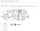
To make any microphone work, including the UP/Down channels, you only need 3 wires. That's correct. Pin 1 = Audio, Pin 3 = TX/Channels, Pin 5 = Shield/ground. Even though the mic plug is a 6 pin, the stock mic that comes with the radio only has a 4 wire cord. There are no wires attached to pins 4 & 6 in the mic plug. They are not needed.
In a nutshell:
At least 2 different mic PCB's:
PCB CBM01 ver 20150820
PCB CBM01 ver 20180813 - has additional 102 from audio (pin1) to ground
mic side pin out
1 - white - audio - 5v goes to high side of electret element
2 - blue - nc
3 - red - ptt - goes to channel resistors and PTT switch
4 - nc
5 - black shrink tube - shield/ground - goes to circuit ground
6 - nc
Channel Up = pin 3>3.9k resistor>momentary switch>ground
Channel Down = pin 3>2.2k resistor>momentary switch>ground
TX = pin 3 switched to ground via PTT switch
Stock mic's electret element impedance = ~1000ohms
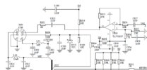
Radio side pin out
1 - audio - 5v phantom DC (blocking cap C900 in radio)
2 - ground - tied to pin 5 and goes to circuit ground
3 - ptt - TX control and channel up/down
4 - Mic Det*
5 - ground - tied to pin 2 and goes to circuit ground
6 - 8v DC- through a buffer can be used to eliminate microphone battery - 7v or 9v
To use a mic with a dynamic element, just put a 104 blocking cap in audio line to keep the 5v off of the dynamic element.
For power mics, you may also want to run a 104 blocking cap in the audio line to keep the 5v out of the mic's amplifier circuit.
Mic's output impedance of 1000 ohms will pretty well match the radio's input impedance.
To run a power mic with a 7v mercury or 9v battery, you can use the 8v on Pin 6 and eliminate the battery (for 7v, use a 1N400x diode to drop the voltage down to ~7.3v).
For mics (hand held or base) that don't have up/down channel buttons, a SPDT MOM-OFF-MOM switch can be mounted and wired to easily provide that function. Here is an example:
https://www.jameco.com/z/1MS4T6B11M...20VAC-28VDC-Panel-Mount_317316.html?CID=MERCH
Pin 3 to switch's center pin, and the 2 resistors for up/down channels to the switch's outer pins and ground.
Radio side mic circuit:


Older mic PCB:

*The only thing I don't know is what "MIC DET" means on pin 4 inside the radio. One of you sharp tech's can probably figure it out. Whatever it is, it isn't used on the stock mic.
I hope this helps someone that wants to get the channel up/down working or experiment with different mic elements to see what sounds best.
Good Luck!
Dr_DX
To make any microphone work, including the UP/Down channels, you only need 3 wires. That's correct. Pin 1 = Audio, Pin 3 = TX/Channels, Pin 5 = Shield/ground. Even though the mic plug is a 6 pin, the stock mic that comes with the radio only has a 4 wire cord. There are no wires attached to pins 4 & 6 in the mic plug. They are not needed.
In a nutshell:
At least 2 different mic PCB's:
PCB CBM01 ver 20150820
PCB CBM01 ver 20180813 - has additional 102 from audio (pin1) to ground
mic side pin out
1 - white - audio - 5v goes to high side of electret element
2 - blue - nc
3 - red - ptt - goes to channel resistors and PTT switch
4 - nc
5 - black shrink tube - shield/ground - goes to circuit ground
6 - nc
Channel Up = pin 3>3.9k resistor>momentary switch>ground
Channel Down = pin 3>2.2k resistor>momentary switch>ground
TX = pin 3 switched to ground via PTT switch
Stock mic's electret element impedance = ~1000ohms
Radio side pin out
1 - audio - 5v phantom DC (blocking cap C900 in radio)
2 - ground - tied to pin 5 and goes to circuit ground
3 - ptt - TX control and channel up/down
4 - Mic Det*
5 - ground - tied to pin 2 and goes to circuit ground
6 - 8v DC- through a buffer can be used to eliminate microphone battery - 7v or 9v
To use a mic with a dynamic element, just put a 104 blocking cap in audio line to keep the 5v off of the dynamic element.
For power mics, you may also want to run a 104 blocking cap in the audio line to keep the 5v out of the mic's amplifier circuit.
Mic's output impedance of 1000 ohms will pretty well match the radio's input impedance.
To run a power mic with a 7v mercury or 9v battery, you can use the 8v on Pin 6 and eliminate the battery (for 7v, use a 1N400x diode to drop the voltage down to ~7.3v).
For mics (hand held or base) that don't have up/down channel buttons, a SPDT MOM-OFF-MOM switch can be mounted and wired to easily provide that function. Here is an example:
https://www.jameco.com/z/1MS4T6B11M...20VAC-28VDC-Panel-Mount_317316.html?CID=MERCH
Pin 3 to switch's center pin, and the 2 resistors for up/down channels to the switch's outer pins and ground.
Radio side mic circuit:

Older mic PCB:

*The only thing I don't know is what "MIC DET" means on pin 4 inside the radio. One of you sharp tech's can probably figure it out. Whatever it is, it isn't used on the stock mic.
I hope this helps someone that wants to get the channel up/down working or experiment with different mic elements to see what sounds best.
Good Luck!
Dr_DX


