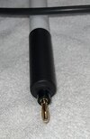
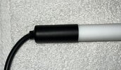
There are multiple ways to build a Capacitor Discharge Stick:
1). Screw drive across the cap and watch the sparks fly.
2). Holding a resistor in a pair of insulated plier and touching the caps needing discharged.
3). Placing your hand or a friends on the caps and hoping for the best.
4). Using a brazing rod wrapped in shrink wrap with a wire connected to an alligator clip.
5). Using two pieces of wire with a resistor in the middle and touching each end of the capacitor.
The only one of those 5 methods I’ve ever used is a trusty screw drive #1 above.
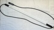
In my search I settled on the following manufactured Capacitor Discharge Stick which is rated to 600 volts. I’ve used it with great success to discharge AC capacitors. A little pricey but it works.


I wanted to build a Capacitor Discharge Stick (know as CDS from henceforth) capable of discharging approximately 4KV as my amplifiers run 3.5-4KV. In my mind I can’t see an entire Bleeder Resistor board going bad. Therefore most of the voltage would be discharged by the working Bleeder Resistors. That said, better safe than sorry. After thoroughly researching the topic here’s the items I decided upon.
Parts List:
1. Teflon/PTFE Rod 2 foot long 1/2 to 1 inch diameter with at least 5/16 to 1/2 hole down center. Purchased from ZORO. McMaster-Carr has some good sizes as well.
2. Resistor…calculate value needed and then 5 watt or 10 watt. I choose these:

3. HV wire. I purchased 15KV and 30KV. Ended up using the 30KV rated wire.
4. Probe of some kind. Banana plug, welding rod, old antenna whip whatever works. I settled on these:

5. Shrink Wrap
6. Soldering Iron
7. Crocodile Clip for attaching to chassis or ground. These are great off Amazon:

The reason for a hole down the center is that I’m using a 3000 ohm ohmite 10 watt resistor. I want the resistor to solder directly to my probe tip which is a banana plug and then slide it up inside the rod.
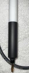
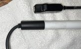
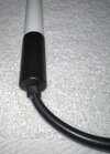
The following photos show the build:

The above banana plug is Flood Soldered and then the capacitor lead inserted.

Then slide the assembly up the center of your Teflon rod.

I would greatly appreciate any feedback for ways to improve and what others see as a hazard that I haven’t considered. Yes please tell me if I have a “FATAL ERROR” in my design/project.


When choosing the value of resistor needed one needs to consider the Ripple Current of the capacitor being discharged. This is provided in the manufactures specifications or can be calculated.
While the above CDS will discharge the dangerous voltage, I use my manufactured CDS for any voltage not discharged. Always verify with the meter on your amplifier or your volt/ohm meter that all voltage has been discharged. Even after that I still use my trusty screw drive to ground the capacitors. Keep in mind that it’s not uncommon for some voltage to develop in a discharged capacitor which is why I use a test alligator jumper to keep the capacitors discharged.
Notes: The hole down the center needs to be large enough for the resistor to slide into. I’ve found that 5/16 is usually large enough. The HV wire isn’t carrying High Voltage because it’s after the resistor. Now if you placed the Resistor at the Crocodile Clip HV is traveling that wire until it hits the resistor.
Most of the time when purchasing wire for around the home or in our autos were more concerned with Amperage rather than Voltage. Amperage is based on guage of wire while voltage handling is based on Insulation of the wire.
Brad
KE0XS
South of Pittsburgh
1). Screw drive across the cap and watch the sparks fly.
2). Holding a resistor in a pair of insulated plier and touching the caps needing discharged.
3). Placing your hand or a friends on the caps and hoping for the best.
4). Using a brazing rod wrapped in shrink wrap with a wire connected to an alligator clip.
5). Using two pieces of wire with a resistor in the middle and touching each end of the capacitor.
The only one of those 5 methods I’ve ever used is a trusty screw drive #1 above.
In my search I settled on the following manufactured Capacitor Discharge Stick which is rated to 600 volts. I’ve used it with great success to discharge AC capacitors. A little pricey but it works.
I wanted to build a Capacitor Discharge Stick (know as CDS from henceforth) capable of discharging approximately 4KV as my amplifiers run 3.5-4KV. In my mind I can’t see an entire Bleeder Resistor board going bad. Therefore most of the voltage would be discharged by the working Bleeder Resistors. That said, better safe than sorry. After thoroughly researching the topic here’s the items I decided upon.
Parts List:
1. Teflon/PTFE Rod 2 foot long 1/2 to 1 inch diameter with at least 5/16 to 1/2 hole down center. Purchased from ZORO. McMaster-Carr has some good sizes as well.
2. Resistor…calculate value needed and then 5 watt or 10 watt. I choose these:
3. HV wire. I purchased 15KV and 30KV. Ended up using the 30KV rated wire.
4. Probe of some kind. Banana plug, welding rod, old antenna whip whatever works. I settled on these:
5. Shrink Wrap
6. Soldering Iron
7. Crocodile Clip for attaching to chassis or ground. These are great off Amazon:
The reason for a hole down the center is that I’m using a 3000 ohm ohmite 10 watt resistor. I want the resistor to solder directly to my probe tip which is a banana plug and then slide it up inside the rod.
The following photos show the build:
The above banana plug is Flood Soldered and then the capacitor lead inserted.
Then slide the assembly up the center of your Teflon rod.
I would greatly appreciate any feedback for ways to improve and what others see as a hazard that I haven’t considered. Yes please tell me if I have a “FATAL ERROR” in my design/project.
When choosing the value of resistor needed one needs to consider the Ripple Current of the capacitor being discharged. This is provided in the manufactures specifications or can be calculated.
While the above CDS will discharge the dangerous voltage, I use my manufactured CDS for any voltage not discharged. Always verify with the meter on your amplifier or your volt/ohm meter that all voltage has been discharged. Even after that I still use my trusty screw drive to ground the capacitors. Keep in mind that it’s not uncommon for some voltage to develop in a discharged capacitor which is why I use a test alligator jumper to keep the capacitors discharged.
Notes: The hole down the center needs to be large enough for the resistor to slide into. I’ve found that 5/16 is usually large enough. The HV wire isn’t carrying High Voltage because it’s after the resistor. Now if you placed the Resistor at the Crocodile Clip HV is traveling that wire until it hits the resistor.
Most of the time when purchasing wire for around the home or in our autos were more concerned with Amperage rather than Voltage. Amperage is based on guage of wire while voltage handling is based on Insulation of the wire.
Brad
KE0XS
South of Pittsburgh
Last edited:


