• You can now help support WorldwideDX when you shop on Amazon at no additional cost to you! Simply follow this Shop on Amazon link first and a portion of any purchase is sent to WorldwideDX to help with site costs.
  • The Retevis Holidays giveaway winner has been selected! Check Here to see who won!

Clarifier unlock for a Kraco KCB-2340 23 channel radio?

doffo

Well-Known Member
Oct 14, 2012
365
284
73
Hello,

I was hoping someone would know how to get the clarifier unlocked on this old Kraco KCB-2340. Tried to do some searching but couldn't find much information on it. I do see just 2 wires going up to the clarifier, so hoping there is a way to just get the TX to follow. The board is a Cybernet PTBM034AOX 23 channel radio. The 2 wires that come off the Clarifier, the one goes up front to the 1st shorter board, and the 2nd wire goes all the way back near the Relay.
====
Update:
Tracing some stuff down, the yellow wire coming off the clarifier has voltage to it, and the red wire that goes all the way back to the relay seems to not have voltage. When you key it, the voltage at the yellow wire up front goes to 2.54v. Unsure what is regulating the voltage when it gets cut off.

I dont think its as easy as removing the ground from the relay and permanently putting to ground, but hope this helps in tracking on how to unlock the clarifier.
====
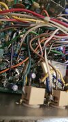
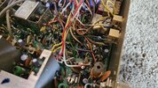
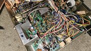
Here are a few pictures of the area:
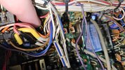
yellow wire 20241014_095812.jpg
yellow wire 20241014_095827.jpgred wire 20241014_100857.jpgred wire 20241014_100919.jpgkraco 2340 20241014_095741.jpg

Appreciate any help on this. Hoping it can be done without too much trouble.
 
Last edited:

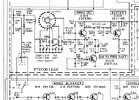
Attaching a PDF of the owner's manual so you'll have a schematic. Schematic shows three wires to the clarifier control, one for RX, which you already found, and one for TX, which is supposed to connect to a fixed point of resistance in the clarifier control, and then one that goes to the varactor in the 14 MHz oscillator.

No idea why you only found two wires going to the clarifier pot. From your description it sounds like the TX side fixed resistance is still there. I've got a PTBM035COX radio that has a similar clarifier circuit. There are two wires going to the normal two out of three terminals you'd expect to see on any potentiometer, and then another contact sticking out the other side of the pot that a third wire goes to. Perhaps your radio has something similar?
 

Attachments

  • Like
Reactions: doffo
Attaching a PDF of the owner's manual so you'll have a schematic. Schematic shows three wires to the clarifier control, one for RX, which you already found, and one for TX, which is supposed to connect to a fixed point of resistance in the clarifier control, and then one that goes to the varactor in the 14 MHz oscillator.

No idea why you only found two wires going to the clarifier pot. From your description it sounds like the TX side fixed resistance is still there. I've got a PTBM035COX radio that has a similar clarifier circuit. There are two wires going to the normal two out of three terminals you'd expect to see on any potentiometer, and then another contact sticking out the other side of the pot that a third wire goes to. Perhaps your radio has something similar?
I looked again at the potentiometer, and its only the 2 wires. It still seems that the red wire is going directly to ground, and when you transmit it disconnects it.

I will have a look at the other model you have and see how close they are. Thanks. :)
 
Ground the RX side of that section of the relay, disconnect the TX side.

Or, unsolder the Red wire back at the relay, solder it to Ground.
Soldered the wire straight to ground, but that hardly makes any changes during transmit. Nothing even noticeable when you adjust the clarifier potentiometer.
 
There is a pink wire to investigate. The schematic in the manual TM86 shared has writing in it that shows numbers by the clarifier wires that I assume correspond to the numbers on the board by the relay. This writing could be wrong, but nonetheless, I would like to know where the pink wire goes. Your image shows the yellow wire coming off R205, which should go to the relay center contact.

There are a couple things standing out. If the numbers in that schematic are correct, the yellow wire is may be going to the wrong relay terminal. It also appears that the yellow and pink wire have been removed and re-wrapped on their pins. Something may have been switched around.

Edit: what NZ8N said should have worked even if things at the relay are messed up, so I don't know. Tying that red wire to ground should make RX and TX the same.
K1.png
 
Last edited:
  • Like
Reactions: doffo
ok... lets say that they didn't have one of those side-tapped pots and had to improvise.

If the TX side of the relay went to the node at R205/R206/R208 via fixed resistor to the back side of the board (where we can't see it in the pics), where the yellow wire comes from, grounding the red wire wouldn't take the TX resistance out of circuit, and it would remain in parallel with the clarifier control even after the recommended change. Clipping the TX wire on the relay may be necessary to take whatever that goes to out of parallel during TX.
Thanks for the tips. Once I get some stuff done this AM I may try that. Only thing that I could think of see where the board gets the voltage from once the clarifier wire is off. This way, you can grab the 5v and feed it into it using the clarifier to that spot... Just thinking out loud. :)
 
Riiiiiiiiiise from your grave..(kinda). well... My own thread lol.

I have a Kraco SSB De Luxe base radio I think I bought off eBay around 2021, and it was modified at some point many years back. Probably before I was ever born lol.

So on top of their crystal mod they did to get channels 36-38, they also had their clarifier unlocked! Same board as the one I was posting about earlier.

I will get some pictures and do some comparisons. All I can see is that they moved a wire on over to the clarifier coming off the Relay that went near the front, but I dont have my mobile Kraco SSB to compare at the moment, but the clarifier does follow both transmit/receive on this base radio. :) I will post on a later day once I can get to the radio in the garage. Currently in a box on the very top shelf so I wouldnt get to it anytime soon lol.
 
No idea why you only found two wires going to the clarifier pot.
I found why that was... There IS 3 wires... DOH!!! The potentiometer on the mobile version has it on the opposite side of the 2 that were there. Goofy setup but there is 3 wires, and I was able to successfully unlock the clarifier. :) I am glad I bought the base Kraco SSB De Luxe back in 2021 or so and just the other day decided to crack it open and see what was done. Sure enough, the clarifier was unlocked on it, so followed the wires back, which led near the relay. Since the area near the front in the mobile version was a tight fit, I just took the lazy way out and snipped the wire near the relay, and bridge the 2 points underneath the board to accomplish the same thing. :)

I will get pictures gathered and do another quick writeup sometime in the coming days.
 

dxChat
Help Users
  • No one is chatting at the moment.
  • @ Crawdad:
    One of the few times my tiny station gets heard on 6m!:D
  • @ Galanary:
    anyone out here familiar with the Icom IC-7300 mods
  • @ Crawdad:
    7300 very nice radio, what's to hack?
  • @ kopcicle:
    The mobile version of this site just pisses me off
  • @ unit_399:
    better to be pissed off than pissed on.
    +1