• You can now help support WorldwideDX when you shop on Amazon at no additional cost to you! Simply follow this Shop on Amazon link first and a portion of any purchase is sent to WorldwideDX to help with site costs.
  • Click here to find out how to win free radios from Retevis!

Cobra 138XLR Audio Problem ?

Switch Kit

Well-Known Member
Apr 6, 2005
3,614
169
63
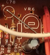
Can't seem to turn the audio down on this one ? in other words , you only need to just crack the mic gain control on AM or SSB using a stock mic ? I really don't know , VR6 doesn't look like it was ever in this radio and there seems to be a jumper across where it would have been . As far as I know the radio has been recapped , the alignment seems on the money , you just cant turn the thing down , The radio for it's age is in very good condition . Running a 2 x 2879 box on SSB with it really seems to heat up the amp pretty quickly unlike other radios used on it . Any ideas on this one would be greatly appreciated . Switch Kit IMG_20230118_113816838[1].jpgIMG_20230118_114829925[1].jpgIMG_20230118_115017248[1].jpgIMG_20230118_120439602[1].jpg
 

Looking at the schematic, ic3 looks like the mic amp. Maybe a cap in backwards around it? Like c47 or c67? R78 is the negative feedback for ic3, looks like it's there, is it cracked? Look at the back of the board in this area with a magnifier, might be a cracked trace. The 858 boards I think are prone to cracking.

Edit: I didn't find vr6 in the schematic, the jumper looks like it might be factory.
 
I noticed from the pics that VR7 in your radio is cranked way over to one side. That's your AMC adjustment. I don't remember if that's cranked all the way up (max modulation) or all the way down in that position, but it's probably not good either way.
 
This is one way a control can fail. A check with an ohm meter can tell you if the connection to the control's ground lug has been lost inside the control. You should read close to zero ohms with the control all the way down, measuring from the wiper (center) lug to the ground side counterclockwise lug.

My first guess as to the cause.

73
 
Can't seem to turn the audio down on this one ? in other words , you only need to just crack the mic gain control on AM or SSB using a stock mic ? I really don't know , VR6 doesn't look like it was ever in this radio and there seems to be a jumper across where it would have been . As far as I know the radio has been recapped , the alignment seems on the money , you just cant turn the thing down , The radio for it's age is in very good condition . Running a 2 x 2879 box on SSB with it really seems to heat up the amp pretty quickly unlike other radios used on it . Any ideas on this one would be greatly appreciated . Switch Kit View attachment 62153View attachment 62154View attachment 62155View attachment 62156

Your Dynamike isn't working because it has been disconnected. I can't see where the leads go but it is probably being used for variable power?

C61 is connected to the junction of D22 & R89

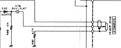
VR6 is the internal mic gain that on the 138XLR and 139XLR has been moved to the front of the radio and called Dynamike. On the 139XLR (base version), because it is a longer run, Cobra used a shielded pair and simply used the 3 holes of VR6 and wired it to the Dynamike pot on the front of the radio.

1674128999767.png

1674129045546.png

On the 138XLR, since the runs are shorter, Cobra just used regular wires coming from the Dynamike pot. I don't have a Sams of a 138XLR or a picture of a stock one, but I have no reason to believe it wouldn't follow the schematic.

1674123198636.png

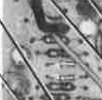
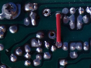
If you want to restore your Dynamike to match the schematic, then remove the jumper that goes across VR6 and the insulated (red) jumper on the bottom of the board where R90 goes, then restore C78 (50v .47) & R90 (4.7k), make sure your Dynamike pot is a 20K B - linear taper. Solder the middle wire (wiper) from the Dynamike to the hole just below "VR6". The white wire in the photo is covering up the other 2 holes. The wire on the high side of the Dynamike goes to the hole where the jumper is currently (lower right end). And the low side of the Dynamike goes to the hole closest to R90 straight to the left of the high side hole.

1674130205637.png

You can see the middle and low side holes here. The middle hole is the top one.

1674130768920.png

Good Luck!
 
Last edited:
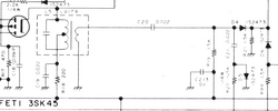
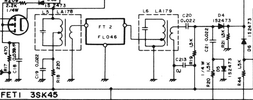
*****This is for anyone that has a 40 channel Uniden Upd858 SSB chassis that is missing FT2 & L6.

You are missing FT2 and L6; this is from the factory.

But if you ever want to add a RX stage and some adjacent channel rejection to your no FT2 & L6 chassis, just get a donor 858 SSB chassis that has L6 and FT2.

NOTE* - Don't make the mistake that most techs/people do and use L6 from the donor chassis. You want to use L5. The L5 on a stock chassis without FT2 & L6, is L6 on a stock chassis with L6.

So you would unsolder your L5 and put it in the empty L6 location and then take L5 from the donor and put it in your L5 position. Re-align.

L5 = LA178 = 7.8Mhz
L6 = LA179 = 23Mhz (N.B)

The folks that published Secret CB back in the 70's came out in March 1978 with a "Super Ears" MOD3 Adjacent channel rejection Kit that has FT2 and a LA179.

They screwed up and should have included a LA178.

1674132657621.png


Good Luck!
 
L6 = LA179 = 23Mhz (N.B
I learned to just stay away from Secret CB because of the typos. By the time I finished correcting one of their procedures I could have done it on my own faster. Just learned to ignore them.

A glance at the schemo reveals that L6 is not a 23 MHz component, but operates at the same 7.8 MHz as L5.

73
@Chris

Thanks!

I do see the same on the schemo as you. You are probably right, LA179 is a 7.8MHz component. And I hear you about Secret CB, my experience has been the same as yours - too many mistakes and a lot of the mods aren't very good.

My comment about the "Super Ears" kit was to that point. It was another of their "mistakes". That is why I haven't used the one I have - it has the wrong coil.

The "23MHz N.B." part came from Ken's Electronics, who sells both LA178 & LA179. Maybe he is wrong.
LA178 7.8MHz; L5-R520 & C139; (not in R510), Robyn LL0075, Cobra 060-025-9-009$5.40
LA179 (23MHzN.B) Robyn LL0057, L2-R505 & C142 & C148; L5-R510, L6-R520 060-025-9-010 046-018-9-002$5.76
My earlier post wasn't about the freq. of the 2 coils, although I do strive to be accurate, it was about the fact that L5 is different depending if FT2 & L6 is present or not and if you are going to add FT2 and L6, to use the correct coil from the donor chassis. Obviously, there is some difference between the two - hence the two different part #'s.

138XLR
1674235374807.png

139XLR
1674235484641.png
 

Attachments

  • P1060080.JPG
    P1060080.JPG
    632.9 KB · Views: 8
  • P1060081.JPG
    P1060081.JPG
    629.1 KB · Views: 7
  • Like
Reactions: NZ8N
First and foremost , thank you all for chiming in on this one . OT03 , pots are all cleaned and C79 and C81 are good . Shade Tree , C47 and C67 are good and no cracks . Nomad and Super Lid , I was truly hoping it was the pot but it checked out 0 to 10K OK .(10K pot) TM86 , VR7 AM audio was up all the way , brought it back some , about 3 to 12 watts pep on AM with mic gain cracked as it is . I did find out why it was turning my AB1 Galaxy 2 x 2879 into a hot iron quickly , SSB on this thing was pushing 25 watts pep , (2166 driving a 1969) turned it down to about 12 watts the problem there was taken care of . (no need to beat up on the antique and that's what amps are for anyway)
Dr DX , from looking at it , the mic gain looks factory and not a variable , as you said and Illustrated and it does make sense to some degree that this hobbyist could change things around for the better ? I really don't have much History on this radio other then it's super clean for 45 sum odd years old , they obviously came from the factor like this so I would certainly think that the mic gain should work properly as is ? Everyone who chimed in made good sense and gave me something to look at , I guess times like these is why good techs make there livings.
A lot of techs these days won't even touch these radios anymore and I can't say I blame them when it comes to parts and time allowed . I personally have a passion for older SSB cb radios , the receive on this radio is outstanding and the channel rejection I couldn't ask for more , audio just cracked open on it's own stock mic on SSB gets me nothing but great reports as well as locally , it's just knowing that something isn't kosher with the mic gain is what it is . Again I say , much thanks to everyone who has tried to help .
 
I have a 138XLR with the same issue. Need to correct it also, as it looks as if someone partially disconnected the pot. On the list.
@Holydvr

Rather than me speculating, would you be willing to crack your 138XLR open and take a pic or two to see if it looks like Switch Kit's? If I had one, I would.

I have a 139XLR and a TRC457 and both follow the schematic (at least for that part of the circuit). Maybe the 138XLR doesn't follow it's schematic.

@Switch Kit - It isn't normal that the Dynamike is that "touchy". Something has definitely been "modified". For sure the solder side jumper with red insulation. It isn't even functional in it's current state. One side is soldered to ground but nothing is connected to the other side. It's not doing anything. It appears to me that part of the circuit was modified twice. Initially, R90 was jumped. This allows the Dynamike to turn "off" the mic audio rather than just turn "down" the mic audio in schematic form. Later the R90 jumper was bypassed all together. BTW, Cobra used bluish-green sleeving on leads that might short out. Also, all the SB's that I can find for that radio, none of them modify that part of the circuit.

Realistic 858's (449, 457, 458), which don't have an external mic adjustment, have a 20K VR6 installed with the low side going directly to ground.

Can you tell us where the 3 leads on the Dynamic go to? That will help us figure out what it is controlling.

Thanks,
Dr_DX
 
Last edited:
  • Like
Reactions: Holydvr
*EDITED for accuracy*
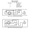
FYI - Also, not all Cobra 4 pin mics are created equal. According to the OM, the 138XLR stock mic is wired for Relay PTT and the 139XLR stock mic is wired for Electronic PTT.

1674262979861.png
 
Last edited:
  • Like
Reactions: tecnicoloco

dxChat
Help Users
  • No one is chatting at the moment.