• You can now help support WorldwideDX when you shop on Amazon at no additional cost to you! Simply follow this Shop on Amazon link first and a portion of any purchase is sent to WorldwideDX to help with site costs.
  • Click here to find out how to win free radios from Retevis!

Cobra 139 XLR Power supply Problem.

Low_Boy

Sr. Member
Jan 21, 2010
1,934
1,196
173
Rochester N.Y.
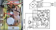
I will admit I know nothing about power supplies. So a odd problem occurred on this radio. The power supply is working while plugged in to AC. I unplugged the AC cord and then Plugged in the 13.8V cord from my power supply and some wires burnt in the power supply of the radio. When this happened it did not blow the fuse in the radio but blew the fuse in the power cord going to my external power supply. The way I am looking at this the AC power supply is good and is still working. The problem is in the DC part. So far the bridge rectifier tests good. And that has nothing to do with DC power. There is a NEC 2SD188 and I am not sure exactly what that does but seems to have something to do with DC. I see someone was in there at least one time before me because a Cap has been changed and there are still remnants of the exploded Cap. I will post some pictures
 

Attachments

  • 20220319_104706.jpg
    20220319_104706.jpg
    1.8 MB · Views: 17
Last edited:

The 2SD188 is one of those TO-3 "cans" or Top-Hat styles.

NTE has got MJ1015 - or a 2N3773 would work...

It's the Power Regulation Pass Transistor.

So it tells me it's an NPN.

But the Bridge is toast.

That usually what happens when the diodes fail from the reverse breakdown - you plug in a power cord - the Bridge is supposed to be rated to withstand it - but in this instance - one of the diodes is shot - blown short. Melting the wire.

You too, have another one of those #$^@*%&! S5VB - Rectifier packs - will have to upgrade to a 100PIV unit.

Why recommend a 100PIV - because of the FLOATING AC presence will "ghost" across into the rectifier - which if still plugged in - will attempt to "float" at that level because of mutual coupling a transformer - like a tube - with try to make all the elements accepting the fields to obtain and hold the charge in a high impedance state - acting like an Open line - stuff - meaning an electrocution hazard.
 
So you think it sounds like the bridge rectifier? The reason I ask is it seems to test good and the radio will still work perfectly when plugged in the wall.
Thanks
 
Contrary to what HA says, if it works when its plugged into the wall, the rectifier bridge and the pass transistor are good. I'm thinking that you had the polarity reversed when you hooked up the External DC supply.

EDIT: I don't have a schematic in front of me, but from your picture it looks like R305 has gotten pretty hot. Might want to check it out

- 399
 
Last edited:
399 that would be impossible . My cobra style power cord is directly hooked to my power supply and has been used for years the exact same way no change. I will look if someone had changed something in the radio. I will check if it can even be plugged in the wrong way. I do not recall the center pin missing. But what you are saying makes sense. I plan on changing everything in there out. Looks like a lot has got hot in there.
 
I just got home and checked out the wiring and from the power plug to the power supply all is correct. I also checked the power socket and the center pin is in it. I also checked to see if the power cord could be plugged in the wrong way and it can not be plugged in wrong.
 
Contrary to what HA says, if it works when its plugged into the wall, the rectifier bridge and the pass transistor are good. I'm thinking that you had the polarity reversed when you hooked up the External DC supply.

EDIT: I don't have a schematic in front of me, but from your picture it looks like R305 has gotten pretty hot. Might want to check it out

- 399
Also have a close look at r302 area behind c302.
Something got hot.
It still works on AC?
One question, does the AC port on the radio have a switch that is depressed when the plug goes in?

73
Jeff
 
Contrary to what people may think - after a closer inspection of your photo - there are several things that looks like someone stuck a paper clip and arced across the rectifier - the "noise filter cap" and the Variable below it - also show scarring from something reached in there and popped while the unit was on.

And also - a Bridge rectifier will still produce DC - but it is not as efficient as it once was - you'll notice this when the power demand sags when it's in use.

1647726501931.png
You have 3 diodes still working - one is open - a direct short across the transformer will eventually cook the short until it's open for good. But if you TESTED the rectifier - it will still show ok, why? Because if the Transformer windings are still connected - it shows the ohmic of the winds and then the actual drop in the other - it looks good, but is it?

Another look would be to remove the part and test it out of circuit - you didn't go into any details, so I'll just figure you unsoldered the leads and tested it that way - did you check for short to ground (the plate it's mounted to?) This case has metal mounting "base" so you know...

1647726021757.png

This is the differences you DONT see when you have a bad bridge rectifier.
Power can still be produced - It Is A Full-Wave Rectifier
Meaning it conducts during the full cycle of AC to develop a
Polarity for DC power.
Just that it is now weakened.
One Diode gone places more demand on the other 3.
The "short" becomes open when left in the state so testing a bridge rectifier is better to simply replace it - at least knowing my experiences with these older units the S5VB is a generic workhorse, but rated for 50PIV @ 5A - about half the voltage it should be rated for.
 
Last edited:
I do know c302 once exploded because someone replaced it with a axial. I read that the rectafier can be checked in circuit. I will take the leads off and check it. It does not short to ground so that is good.
 
  • Like
Reactions: Handy Andy
I was wondering is this bridge rectifier even hooked up correctly? The two red wires come from the transformer. I am thinking hot and neutral. The black and orange wire go to the board. The flat corner is the +. I am thinking this is wrong? Am I wrong but should one red go to the notched corner and the other red to where the black is? Orange and black I am not sure?
Thanks.
 

Attachments

  • 20220320_141730.jpg
    20220320_141730.jpg
    1.4 MB · Views: 8
Last edited:
I was wondering is this bridge rectifier even hooked up correctly? The two red wires come from the transformer. I am thinking hot and neutral. The black and orange wire go to the board. The flat corner is the +. I am thinking this is wrong? Am I wrong but should one red go to the notched corner and the other red to where the black is? Orange and black I am not sure?
Thanks.
The bridge has a tiny + symbol were the orange wire is, that should feed a trace that goes to the + side of that filter cap.
The opposite corner is negative.
The 2 reds are AC coming from the secondary of the transformer, there is not so much a hot and neutral as they are both "hot" .
It looks correct from here.
Be easy to replace the bridge, have you looked at the bottom of the power supply board?
Just to check the work done when the cap was replaced.

73
Jeff
 
  • Like
Reactions: NZ8N
The bridge has a tiny + symbol were the orange wire is, that should feed a trace that goes to the + side of that filter cap.
The opposite corner is negative.
The 2 reds are AC coming from the secondary of the transformer, there is not so much a hot and neutral as they are both "hot" .
It looks correct from here.
Be easy to replace the bridge, have you looked at the bottom of the power supply board?
Just to check the work done when the cap was replaced.

73
Jeff
Yes very sloppy. Never cut the legs sticking through the board. I think I am going to replace everything but the 2SD188. Most of the resistors look like they have gotten pretty hot. There is also a 2SC1419. I am going to up the wattage on all the resistors. with 1/2 or 1 watt. This is a friends radio and I am trying to keep the parts price down.
 

dxChat
Help Users
  • No one is chatting at the moment.