• You can now help support WorldwideDX when you shop on Amazon at no additional cost to you! Simply follow this Shop on Amazon link first and a portion of any purchase is sent to WorldwideDX to help with site costs.
  • The Retevis Holidays giveaway winner has been selected! Check Here to see who won!

Cobra 142GTL My next project, Unable to get CT3 into spec.

Hey Nomad,
So checking the frequency at TP1, Channel 19 USB Mode and adjusting L19 or L20 makes no difference on the frequency at TP1. The only adjustment that changes is CT3.
It was worth a shot.
 
There's alot of pieces part's between the clarifier circuit, D37 and TP1 to turn over the turnup truck.
One thing i see as well is the IC1 VCO-Mixer list in the sam's book is a UH1C007 and what's in it is a UH1C070,
I just pulled C-66 that is a 10 VDC cap to dig out more sony bond i missed around that area and the around IC1, I've swapped out the different number's of IC1 and never seen a difference coming off CT3.
Another thing i did was to attach a 10Pf cap where C132 would go with no difference in the CT3 setting
I will be putting in a 1000Uf 35VDC cap back in C-66 when i get the sony bond all cleaned out.
 
Hey AS.
Yes there is a place for C-132 and in my previous messages i did install a 10Pf Cap there it's marked on the silk screen with no difference in the CT3 calibration, I was referring to the link in Secret CB that said to remove CT3 and C-132 and why it was suggested.
I did remove CT3 before and it's still not showing the 34.987500Mhz and the radio is not in tune.
 
The adventure continues.
I original replaced red 20Pf CT3 with a yellow 40Pf cap, It won't come in tune, I pulled it and installed a blue 5Pf one, same thing, I pulled the blue and installed a brown 60Pf one, Same situation. I pulled another CT1 or 2 off another 142GTL board and installed it, Since all 3 CT's are the same P/N. Same situation.
I don't remember where i got these cap's and all i know is the maximum Pf on them only the max.
It seames like what ever PF cap i install just won't get me to the 34.987500 Mhz frequency i need.
I do know this, If a guy ever wanted a 142GTL that transit's on the zero's. I can make arrangement's for you to get one.
One thing is in question about D37 Varactor Diode,
The sams book list 3 replacement's, 1S2687D and the 1S2686 These 2 cross to the NTE612 which are suspost to be 12Pf 4 volts, The third one listed is a 1S2687 that crosses to a NTE614 which is suspost to be a 33Pf 4 volt, Now i know the D-37 i pulled was marked 87D, but to be able to test it is above my pay grade.
I pulled some 86D varactor diodes from some other boards and figured a easy way to try out the D-37. Just solder then to the trace on the bottom side, I tried many that i had and i figured if there installed backwards, the 34.9848700 speck off TP1 was not adjustable adjusting CT3,
I even tried one time with out a D-37 in it and my reading at TP1 was 35.00279 LOL,
I even soldered down a new NTE-612 and it made no difference.
And the story goes on, I may put it off to the side and take a look at this Pace Sidetalker 1000B i have with the 40 channel NDC40013 PLL in it,
 
I am assuming that the "clarifier" knob is at 12 o clock when you are doing all of this.
So, how far do you have to turn the knob to get to 34.987500Mhz?
 
Hey Kop.
The clarifier is at 12 O'Clock when i try and adjust CT3 and i can not get it to 34.987500 by moving the clarifier.
So i was experimenting with this NTE612 that i had soldered to the board and i thought of this, I took a 1Pf cap and added it in series to the NTE612 varactor diode and the CT1 value dropped from the 34.987500. I threw in a 3Pf and it dropped more, So i macgyvered the 3Pf cap to the original D-37 varactor diode in Parallel and tested and i got it to the 34.987500, I then adjusted the lsb and am and now it's dead keying on the proper frequency instead of being 5Hz off.
I then checked the unlocked transmit and it slides 2Hz both way's? Not as much as i would want, I did test the other 142GTL and it slides down 5Hz and up 2Hz, I do have some of the 5.6Uh chokes all the clarifier mod's i read to put in parallel with the D-37 varactor diode,
I'll give the choke a shot and with it, the 3Pf cap and the varactor diode and see what comes up. It may not be purdy, But as long as it work's rite.
One thing i did think of would be to find some lower or higher Pf Varactor Diodes and eliminate the 3Pf cap in parallel i put on D-37, Just a thought.
 
The other 142GTL is one from the same customer that has a channel switch with added xtal's that is a tuned and working unit.
In the mystery of why the 2nd 142GTL wasn't tuning properly i did notice that the working 142 had a choke on D-20? No idea why but i did pull it and put it in the non working 142 at the D-37 location and it did not make a difference in the CT3 alignment spec. So i reinstalled the choke and Diode in it's D-20 location.
 
When varactor diodes are operated at a lower voltage, their change in capacitance varies at a steeper rate for a given change in voltage. This is the purpose of removing R187, and the added inductance compensates for running the varactor at a lower capacitance/higher reactance. The problem you are having is that you reach a point where the oscillator simply shuts down because the crystal load capacitance is insufficient.

When adding a capacitor in parallel to CT3, you are bringing the pF back up/reactance back down, which does the opposite of removing R187, and as a result, you will once again lose the slide.

You might be able to increase the collector current in the oscillator to help it stay running with the lower pF value, but at the end of the day, stability goes out the window, phase noise goes up, and I think you should just try a different crystal and leave things alone.
 
Hey Brandon.
In post #1 i mentioned i did pull the original 11.325 Xtal and it was out of freq, I purchased a new 11.3258 xtal from 6 star on e-bay, So trying a new xtal was already done.
 
  • Like
Reactions: brandon7861
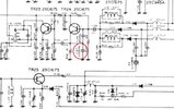
C142 Tripler Oscillator.jpg
142 Tripler Offset with Clarifier. Notice C127 (220pf) from Emitter to Ground.

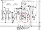
C2000 Tripler Oscillator.jpg
C2000 (148 et al) has a second varactor circuit in place of the 220pf above, added to the Emitter of the 11 MHz oscillator, this is what gives the 2000/148/Grant the extended slide range, compared to the 142/Washington.
 

dxChat
Help Users
  • No one is chatting at the moment.
  • @ Crawdad:
    One of the few times my tiny station gets heard on 6m!:D
  • @ Galanary:
    anyone out here familiar with the Icom IC-7300 mods
  • @ Crawdad:
    7300 very nice radio, what's to hack?
  • @ kopcicle:
    The mobile version of this site just pisses me off
  • @ unit_399:
    better to be pissed off than pissed on.
    +1