• You can now help support WorldwideDX when you shop on Amazon at no additional cost to you! Simply follow this Shop on Amazon link first and a portion of any purchase is sent to WorldwideDX to help with site costs.
  • Click here to find out how to win free radios from Retevis!

Cobra 2000 GTL no 7.800 MHz at TP3

Crambone

Well-Known Member
Jan 22, 2019
516
160
53
56
I am seeing an issue so I was probing around and checking some Test Points and I’m seeing 2MHz on TP3 on USB and CT2 does nothing to affect TP3. This radio wasn’t working from the beginning and I found a few issues, it had the clarifier mod that I removed it was just sloppy and I don’t need. So it was keying around 1.2 watts and would slowly drop down to 0 watts. I found someone removed V10 & C186 we’re just missing. I pulled an old V10 from a parts radio and installed a new cap and now it sits at 2watts no drop off.
I was originally seeing and still do see channel 1-13showing normal frequency but 14-28 are all wrong the 29-40 are good.
I believe this may be associated to TP3 not getting 7.8MHz?
So what direction should I start testing I’m not sure where TP3 actually gets the 7.8MHz from? I did pull the 7.8MHz crystal and it’s showing 7.8013MHz that I assume is fine.

Andrew
 
Last edited:

A couple of questions if you don't mind...
When you were testing TP3.... were you in AM or sideband?
The reason I ask.... TP3 is right in line with the receive IF strip.

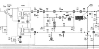
In sideband, the 7.8 Mhz IF is fed down the line and winds up at TP3.. again, this is a receive test point. In AM however an additional 7.345 Mhz oscillator is enabled that beats the 7.8 Mhz down to a 455 Khz IF and the 7.8 Mhz feed is shunted to ground... so you would not get 7.8 Mhz at TP3 in AM.... only 455 Khz.

Looking at steps 9 and 10 in the synth alignment procedure.... they specify USB for step 9 and LSB for step 10. The AM setting is checked at TP14.

So that is why I am asking... just to be sure that I understand your testing conditions.

-----
I attached the IF section that I am working from......

In AM the 455Khz IF would be coming from L15 and piping through headed for TP3 while anything coming out of L14 would be switched to ground by D24 when the 8.17 AM voltage is up on ckt trace 5. With that I would not expect 7.8 Mhz at TP3.

Others who may see this.... please shoot me down if you need to!!! I'm still learning too!

Bob
 

Attachments

  • Cobra2000_IFSection.png
    Cobra2000_IFSection.png
    121.5 KB · Views: 4
  • Like
Reactions: NZ8N
Bob, yes I was testing in USB. I ended up following the synthesizer alignment as this radio seems to have had a lot of fingers inside.
The one issue I’m having is when following the alignment I can’t use channel 1 or 19 they aren't on frequency so I was using channel 2 and 13 and following the Truth Chart.
I had good results until I got to the TP3 7.8MHz in USB.
 
If you are getting channels 14 to 28 to be 29 to 40, then you will have to check your PLL against the truth chart in the service manual, pins 10 through 16.

Either the channel sector is bad, or the radio has been modded for extra channels at the PLL.

Check the PLL traces for cut traces or solder blob shorting the control pins 10 through 16 on the PLL.

If the radio transmits (on any 11-meter frequency) then the 7.8MHz signal is there and you are not reading it properly, I usually solder a small wire at TP3 just to make it easier to connect to from the component side.

When you say "V10", did you mean "VR10" the AM power control? Is it possible that there were wires on the trace side of the radio going to a knob on the front of the radio to control "VR10"? Or it's possible that someone started to do that mod and ended up with the same problems you are having now and went no further ..... or then again it may have become a parts radio for someone and those parts were just taken out for another radio.

It's just a synthesizer you'll get, it's a matter of finding all the problems someone else created.

Good luck ..........
 
This kind of radio will prompt me to ask the radio's owner how many failed attempts at repair have been made since it first broke down? Figure at least one additinal failed circuit in the radio for each of those attempts, on top of whatever it was that failed at first.

When too many of the blocks in the block diagram are broken you're stuck with verifying individual circuit functions on their own one by one.

If you have an oscilloscope have a look around TR31 emitter. Should have the correct carrier frequency for USB and LSB on receive, and the 7.800 MHz on AM transmit. If the DC voltage there changes when you change SSB modes, I'd be looking for a stray glob of solder bridging adjacent foil traces or some kind of accidental sabotage fault.

Emitter should show zero until you key the mike in AM mode.

73
 
  • Like
Reactions: Cable Guy

dxChat
Help Users
  • No one is chatting at the moment.
  • @ Crawdad:
    One of the few times my tiny station gets heard on 6m!:D
  • @ Galanary:
    anyone out here familiar with the Icom IC-7300 mods
  • @ Crawdad:
    7300 very nice radio, what's to hack?
  • @ kopcicle:
    The mobile version of this site just pisses me off
  • @ unit_399:
    better to be pissed off than pissed on.