• You can now help support WorldwideDX when you shop on Amazon at no additional cost to you! Simply follow this Shop on Amazon link first and a portion of any purchase is sent to WorldwideDX to help with site costs.
  • Click here to find out how to win free radios from Retevis!

Cobra 2000 GTL power issue

Smokinone

WDX-3820
Jun 24, 2020
847
1,073
153
Southern Nevada
I've a Cobra 2000 that I have a question on the DC power. When hooked up to AC, the power switch turns the radio on and off as it should. However, when the DC power cord is connected, the power comes on and stays on...no matter the switch position. I think I read somewhere that the 2000 does the power a little different that was causing the meter lights to glow, and something about going to ground to power up rather than through the positive. If that makes sense, it is just a thought I had but don't remember what the particulars are.
I guess what I'm looking for is a little help maybe on where to try and track this issue down...unless it's supposed to stay on with the DC cord attached, which I kinda doubt.
This radio also has a UFO Super Star 1604 installed that doesn't seem to lock when powered on until the mode switch is switched back and forth. Probably doesn't have anything to do with it, but just want to get all the conditions included.

Thanks.
Posted pics of the DC - AC switch.

DSC04073.JPGDSC04074.JPGDSC04075.JPG
 

What's different about that power switch is that it breaks the negative side of the power supply circuit, not the positive side like every other base station you ever saw. The reason for this is that it allowed them to turn the radio on from the alarm clock without using a relay. A short between the power supply's negative side and the radio's chassis might do this.

Not a common fault. If the power switch shuts the radio down in AC-power mode, the switch is not likely the cause. Good thing, since you can't get a new replacement.

Unplug the radio and see if a meter shows continuity between the negative pin of the DC power jack and the chassis. It shouldn't.

73
 
Thanks Nomad. I noticed when tracking the positive lead and it goes into the freq counter it looks like. A check between the chassis and ground pin of the DC is right to ground. I don't see anything obvious after looking over the top and bottom. Will keep going on it. I think I will remove all the added junk and see where it goes. Any thoughts would be appreciated.

Probably the least of my worries now though. My father in law put a super star 1604 at one time. He never did get it working correct, and I can't either. Sometimes it locks and sometimes not. I'm thinking I need to pull it and put it back to an original state. The instructions just call for 2 resistors to be removed, but he took the whole PLL section out. I think I have an MB8719, I ordered the resistors and caps to put those back. The only thing I am lacking is the 10.24 crystal.
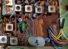
A couple of pics of where the SS1604 are attached to TP-9/10. Also the area where the X-tal and MB8719 were housed.
It looks like he attached 3 capacitors 1 ea at the mode switch for LSB-USB-AM positions, and also added a resistor at the TP9 input. I removed all that at one time, and still won't lock the VCO. The last time I got it to lock the receive would drop out after a short time. A touch of the undeside of the board near the receive section would bring it back temporarily.
I did have contacts with a couple members in the last couple of days, so when it does lock it works, and not when it don't.
I have also recapped the 2000 just to be sure. It's a Taiwan radio.

2000_board_2.jpg2000_board_3.jpgDSC02608.JPGDSC02609.JPG 8719.jpg
 

Attachments

  • 8719.jpg
    8719.jpg
    909.6 KB · Views: 6
Let me ask this. When I did have the VCO locked, I had a reading on pin1 of the VCO @ 7.7 or so volts. Now that I have done something, I don't know what, I have no reading of the 7.7V at pin1. I have the 7.7V at TP9 from the 1604. TP10 has 0V.
R104 and R207 have been removed which takes out the missing 10.24 circuitry and 8719 that was originally there.

At one time I had;

pin1 - 7.75 now 0v
pin234 - 0V now 0v
pin5 - 0v now 0v
pin6 - 0v now 0v
pin7 - 0v now 0v
pin8 - 7.9 now 0v
pin9 - 7.22 now 0v
pin10 - 3.94 now 0v

I am wondering now if I somehow ruined the VCO?
Adjustments @L20 & L19 make no difference.
Thanks for any input.
I also uploaded the install for the Cobra 2000, which I think is correct as it was working somewhat initially. Just wouldn't lock up the VCO until the mode switch was moved back and forth.
 

Attachments

  • 16040001.pdf
    584.1 KB · Views: 4
All those zero-Volt readings mean you have lost power to the PLL section. Turning slugs won't accomplish a lot until the PLL circuit has juice. Time to check pin 1 of the MB3756 chip IC4. If you have 8 Volts DC there, the connection has been broken somewhere between IC4 and the PLL section. If IC4 has zero Volts on pin 1, that's a bad sign. The MB3756 slowly gets harder to obtain with each year that goes by. If IC4 pin 1 reads zero and pin 6 has 13.5 (or so) Volts DC on it, the chip has failed. And if there is nothing feeding into pin 6, power feeding into IC4 has been interrupted and it might still be okay.

73
 
Last edited:
Thanks Nomad. I just checked the MB3756 and have the following.

1 - 8V
2 - 13.5
3 - 8V
4 - 0V
5 - 13.5
6 - 8V
7 - 0V
8 - 0V

Those voltages seem to be correct.

I checked that initially, but just checked again to be sure. I have seen the 3756 fail before. The way I was looking at it I was thinking (assuming) the VCO (UHIC007) was getting it power from the TP9 which ties directly to pin 5 of the VCO.
I believe this 1604 takes the place of the PLL section as the original 8719 or 8734 has been removed and the 1604 inserted in it's place by removing the R104 & R207.

The base of TR20 has 0V as well. Looks to be fed? by R102, but there is nothing there as well. R102 shows to be coming from an 8V source supply voltage, through the resistor to the base of the TR20.
 
Thanks Nomad,
You were right on the power getting lost. I found that the connection marked in the uploaded photo was the problem. Although the trace had been scraped and soldered to the component, it wasn't making a connection. I put a piece of lead across the offending trace and the radio came back to life.
Now to try and get it aligned as the receive audio seems to drop as the radio receives and is on for a few moments. I'll go back and check the voltages and signals.

power issue.jpg
 
  • Like
Reactions: doffo
Next dilemma, When I get to stage 10 of the synthesizer alignment my readings go bad. Up to that point all is good. It calls for TP3 to be at 7.8015, and I'm not really getting anything. Same with all 3 stages at TP3 align.

synthesizer_step-10.jpg
 
Checking the carrier oscillator is a pain. A frequency counter sensitive enough to display a stable reading is hard to find. We use a receiver that has had its frequency calibrated. I use a 1 kHz oscillator in a box with a speaker. It's crystal controlled, so the 1 kHz is within =/- 1 Hz. Tuning in the crystal's carrier on the receiver using LSB, I tune the radio 1 kHz higher. That should get a tone out the speaker that's 1 kHz when the crystal is adjusted properly. Turning on the tone box, you hear a beat note equal to the difference between the two tone pitches. Setting the crystal's trimmer cap to bring the two tones to the same frequency is just faster than wating for a counter to settle down.

Used to have a communications service monitor that contained a receiver and had a LED on the front that would display the audio beat between the signal you're eavesdropping on and the monitor's calibrated internal frequency. A true "zero beat" is hard to hear on a small speaker, but was visually easy to see on the LED.

Putting a preamp on a counter sometimes helps. Just the same, it occurs to me to wonder if the 7.8xx MHz crystal is running at all. Do you get the characteristic "hiss" in sideband receive when switching from AM? If not, maybe the crystal isn't oscillating at all.

That would prevent a proper counter reading. Touching the tip of a 'scope probe to an oscillator circuit can also change the crystal's frequency when you unhook it. If you have a ham type receiver handy that can tune in 7.8015, use one sideband mode. If you hear the tone pitch change when the probe is touched or unhooked from the test point, that means your counter reading is only correct until you remove the probe from the test point.

But finding out if that crystal runs at all is the most important thing to find out first.

73
 
  • Like
Reactions: Cable Guy and doffo
Thanks Nomad.
I got to probing around the 7.8 x-tal and found it was @ 7.798 ish at D39 and D41. Further put the counter probe on the CT3 that is the adjustment for USB @TP3. Something seems to have changed just in hitting the CT3 with the probe, looking down from the front there is a little pad I put the probe tip on. The receive came up, and I was able to do some adjustment while the probe was on the CT3. I then put the probe on TP3 and had my 7.8. I was then able to adjust the USB with CT3, and also LSB with L30. I don't know what exactly what happened in that instant, but I will keep testing to see if it's consistent.
This is inconsistent though it seems as now it is back to jumping around from 6.9 to 7 mhz @ TP3 instead of the 7.8015 with an X1 setting on the probe. I was using a X10 setting initially before it dropped out again.
I can't seem to duplicate getting the adjustment back to CT3 at this point, so I'm back with the same problem. The D39 reading at 7.798 does not vary and is constant.

I use an inherited SM-2420 Heath/Zenith frequency counter...it seems to be more sensitive than my B&K 1805 which I really like.

Thanks for sticking with me, you don't know how much I appreciate it. Keeps me interested and away from the BFH.
 
I use a LNA between a 10x probe and my counter when 10x alone shows 0hz and 1x shows an unstable frequency. Probably not exact to the Hertz given the effect of capacitance of the probe, but reports say SSB is on frequency.
See this thread for useful info...


So, it does work for me, maybe I'm lucky, but I set the frequency counter to 50 ohm going into the LNA and use 10x on a good probe to take measurements. Again, it's not perfect, but it is close enough that I don't worry about it. I just had to do this on a 2000gtl a few weeks ago to get the 7mhz adjusted. YMMV. Good luck.
 
  • Like
Reactions: Smokinone
Thanks. I was able to get the 7 MHz on a V3165 counter. So that issue is solved. The sound issue, really something that I had thought I did, was cured by cleaning the SP 1+2 switch it seems.
This 1604 still doesn't lock on start, but will after moving the mode switch back and forth.
I guess that will have to do, or convert it back to stock. But for now it's working, was able to have a nice QSO with 630 this morning so it's functioning as it should once I get the lock.
Appreciate all the help and suggestions.
 

dxChat
Help Users
  • No one is chatting at the moment.
  • dxBot:
    Greg T has left the room.
  • @ BJ radionut:
    EVAN/Crawdad :love: ...runna pile-up on 6m SSB(y) W4AXW in the air
    +1
  • @ Crawdad:
    One of the few times my tiny station gets heard on 6m!:D
  • @ Galanary:
    anyone out here familiar with the Icom IC-7300 mods